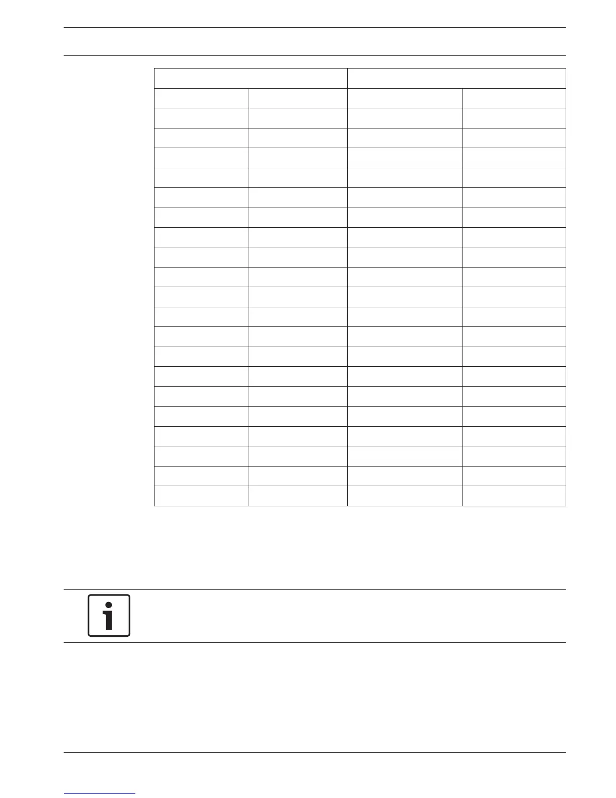
Parallel inputs Parallel outputs
Pad Pin Pad Pin
VC+ 1 VC+ 1
U00 2 D00 2
U01 3 D01 3
U02 4 D02 4
U03 5 D03 5
U04 6 D04 6
U05 7 D05 7
U06 8 D06 8
U07 9 D07 9
GND 10 GND 10
VC+ 11 VC+ 11
U08 12 D08 12
U09 13 D09 13
U10 14 D10 14
U11 15 D11 15
U12 16 D12 16
U13 17 D13 17
U14 18 D14 18
U15 reserved D15 reserved
GND 20 GND 20
Table 6.35: Parallel inputs and outputs
The parallel inputs do not only control the associated parallel output on the same data
distribution board.
They also control the associated parallel outputs on all other data distribution boards that are:
– In the passive mode and do not have address 253, 254 or 255.
Notice!
Do not use a parallel output for more than one purpose.
For example, parallel input D00 of a distribution board does not only control parallel output
U00 of the same data distribution board. It also controls all the parallel output U00 of all the
other data distribution boards that are in the active mode or in the passive mode and do not
have address 253, 254 or 255.
Refer to the figure for the physical connections of the parallel inputs.
Conference System Connection | en 157
Bosch Security Systems B.V. Operation Manual 2013.11 | V2.0 | DCN-NG_OM_V4.x
 Loading...