PRS-NSP Network Splitter
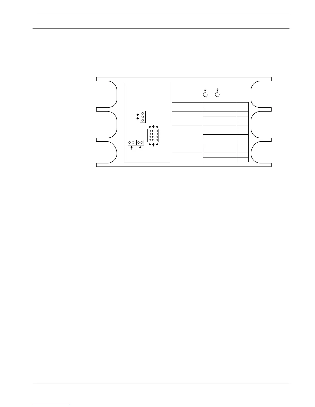
The rear of the cover of the network splitter shows a label that gives data of the internal
connections. You can change the internal connections with the jumper blocks inside the
network splitter.
Figure 7.27: Label inside network splitter
To supply additional power to the tap-offs that are connected to the network splitter:
1. Put jumper shunt 1/2 on position 2.
2. Put jumper shunt 9/10 on position 9.
3. Connect an external power supply to the network splitter (refer to PRS-FINNA Fiber
Interface, page 149).
7.17
Conference System Configuration | en 227
Bosch Security Systems B.V. Operation Manual 2013.11 | V2.0 | DCN-NG_OM_V4.x








 To Next Page