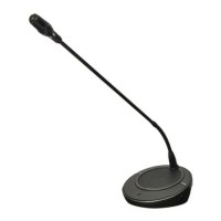
Figure 3.39: Bottom view
1. Condition LED - Shows the condition of the voting panel.
2. Voting buttons - Operate the voting panel. Each voting button has a yellow LED. The LED
shows the condition of the voting button.
3. Card reader - Gives access to the voting panel.
4. External contact plug - Connects the voting panel to an external contact.
5. Solder spot - Configures the external contact plug.
6. RJ11 sockets - Connects the voting panel to the DCN-DDI Dual Delegate Interface and
the DCN-FMICB Microphone Control Panel.
The following sections give more information about the mentioned subject:
– Installation: DCN-Flush mounted products, page 103.
– Connection: DCN-FV(CRD) Voting Panel, page 135.
– Technical Data: DCN-FV(CRD) Voting Panel, page 284.
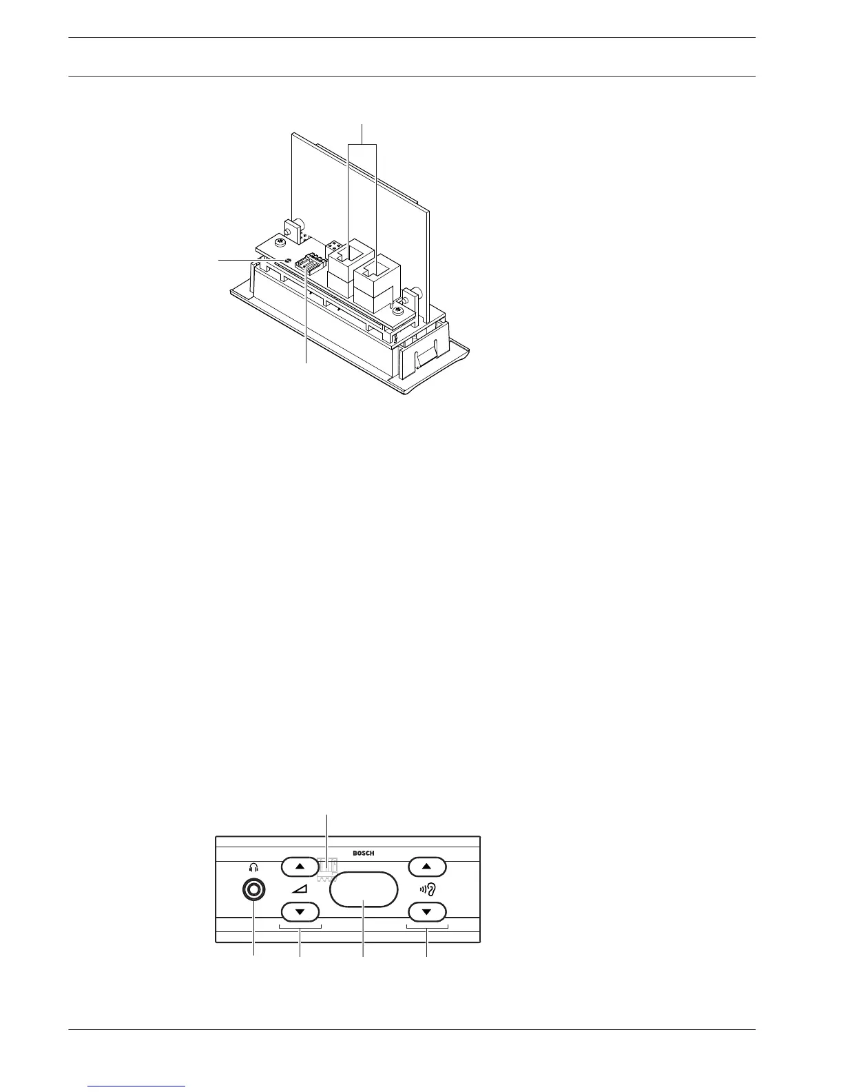
DCN-FCS Channel Selector
With the DCN-FCS Channel Selector, delegates and chairmen can select a channel to listen to.
Figure 3.40: Front view
3.20
44 en | System Overview Conference System
2013.11 | V2.0 | DCN-NG_OM_V4.x Operation Manual Bosch Security Systems B.V.