1. On/Off LED - A green LED is on when:
The power cable is connected to the mains power supply.
The trunk cable is connected to the system.
The central control unit is started.
2. DCN cable - Connects the extension power supply to the trunk of the DCN system.
3. DCN socket (trunk) - Makes a loop-through in the trunk of the DCN system.
4. DCN sockets (tap-off) - Make tap-offs in the DCN system. The socket regenerates the
DCN system signal.
5. Power inlet - Mains power supply connection.
6. Fuse holder - Prevents damage to the internal power supply unit of the extension power
supply.
The following sections give more information about the mentioned subject:
– Installation: DCN-EPS Extension Power Supply, page 109.
– Connection: DCN-EPS Extension Power Supply, page 144.
– Configuration: DCN-EPS Extension Power Supply, page 226.
– Technical Data: DCN-EPS Extension Power Supply, page 286.
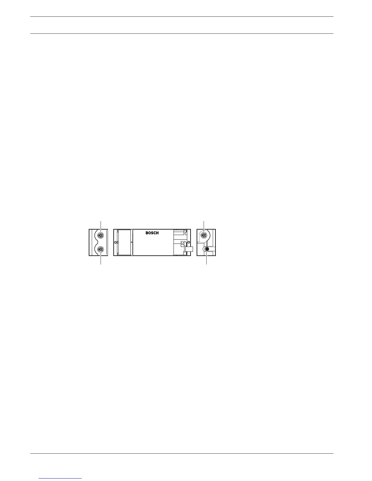
LBB4114/00 Trunk Splitter
Use the LBB4114/00 Trunk Splitter to divide the DCN trunk.
Figure 3.57: Top and side views
1. DCN socket (tap-off 1) - Makes a tap-off in the DCN system. The socket regenerates the
DCN signal.
2. DCN socket (tap-off 2) - Makes a tap-off in the DCN system. The socket regenerates the
DCN system signal.
3. DCN cable - Connects the trunk splitter in the trunk of the DCN system.
4. DCN socket (trunk) - Makes a loop-through in the DCN with the trunk splitter. The socket
does not regenerate the DCN system signal.
The following sections give more information about the mentioned subject:
– Installation: LBB4114/00 Trunk Splitter, page 110.
– Connection: LBB4114/00 Trunk Splitter, page 146.
– Technical Data: LBB4114/00 Trunk Splitter, page 286.
3.28
54 en | System Overview Conference System
2013.11 | V2.0 | DCN-NG_OM_V4.x Operation Manual Bosch Security Systems B.V.
 Loading...