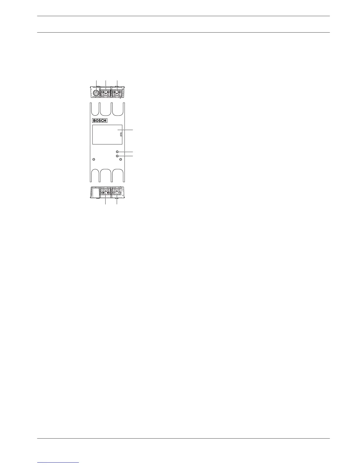
Figure 3.61: Front, rear and top views
1. External power supply socket - Connects the network splitter to an external power
supply. The external power supply supplies power to the tap-offs. It does not supply
power to the trunk.
2. Optical network socket (tap-off 1) - Makes a tap-off in the optical network. The socket
has a maximum load of 2.5 A that gives protection against short-circuits.
3. Optical network socket (trunk) - Connects the network splitter to the trunk of the optical
network.
4. Lid - Gives access to the controls inside. The rear side of the lid contains a label with an
explanation about the internal settings.
5. Status LED - A yellow LED that gives information about the condition of the network
splitter.
6. Status LED - A green LED that gives information about the condition of the network
splitter.
7. Optical network socket (tap-off 2) - Makes a tap-off in the optical network. The socket
has a maximum load of 2.5 A that gives protection against short-circuits.
8. Optical network socket (trunk) - Connects the network splitter to the trunk of the optical
network.
The following sections give more information about the mentioned subject:
– Installation: PRS-NSP Network Splitter, page 111.
– Connection: PRS-NSP Network Splitter, page 146.
– Configuration: PRS-NSP Network Splitter, page 227.
– Troubleshooting: LBB4114/00 or LBB4115/00 Trunk Splitter, page 266.
3.33
Conference System System Overview | en 57
Bosch Security Systems B.V. Operation Manual 2013.11 | V2.0 | DCN-NG_OM_V4.x