60
55
50
45
75
70
80
85
65
40
Y: Power (Watt)
35
30
25
20
15
10
20 40 60 80 100 120 140 160 180
X: Extension cable (m)
DCN-CCU2, DCN-CCUB2, DCN-EPS
200 220 240 250
5
0
6
11
16
21
27
32
38
43
49
54
60
65
70
76
81
6
12
18
24
30
36
42
48
54
60
66
72
78
84
6
13
20
26
33
40
46
53
60
66
73
80
7
15
22
30
37
45
52
60
67
75
82
8
17
25
34
42
51
60
68
77
85
9
18
27
36
46
55
64
73
83
10
20
30
40
50
60
70
80
11
21
32
43
54
65
76
12
24
36
48
60
72
84
13
26
40
53
66
80
15
30
45
60
75
17
34
51
68
85
18
36
55
73
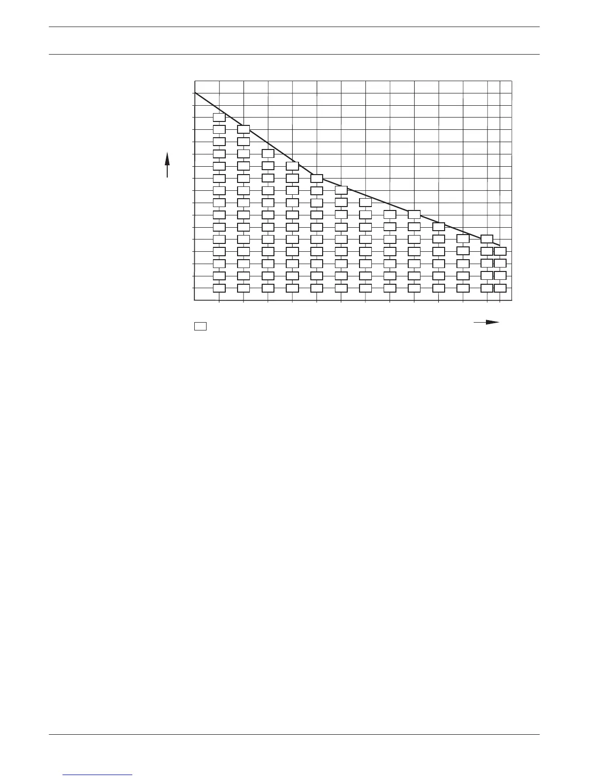
Figure 4.4: Power correction graph
Graph
The power correction graph corrects the power level to compensate for the extension cables.
Do as follows:
1. Find the total power consumption (as explained in the previous chapter ‘Total power
consumption’) on the vertical axis (Y) of the power correction graph. For example, 40 W.
2. Find the length of the longest extension cable sequence on the horizontal axis (X) of the
power correction graph. For example, 60 m.
3. The intersection of both values gives the necessary power from the socket. In this
example it is 53 W.
4. The maximum power from a DCN socket of the central control unit or the extension
power supply, is 85 W. The necessary power from the socket should not exceed this. This
example with only 53 W is therefore within the system limits.
The intersection of both values gives the necessary power from the socket. In this example it
is 53 W.
70
en | Planning Conference System
2013.11 | V2.0 | DCN-NG_OM_V4.x Operation Manual Bosch Security Systems B.V.
 Loading...