13
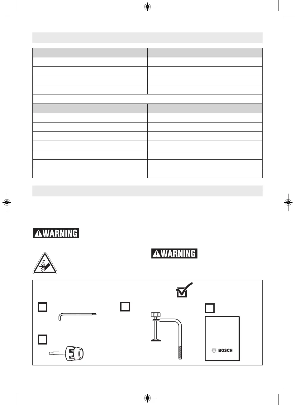
Unpacking And Checking Contents
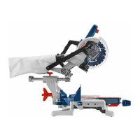
Unpacking the Miter Saw – When removing
this tool from packaging materials, reach down
to the two side carry-handle locations and
slowly lift until it clears the package.
To avoid severe pinching,
never lift or move this
saw by gripping any component of the mech-
anism support system.
This symbol is placed at various lo-
cations on the tool to warn the user
of pinch-point areas.
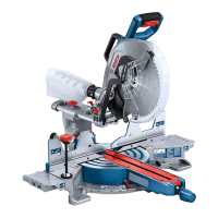
Checking Contents in Package – Open the top
of the package and look for the included loose
parts. Refer to the diagram below.
Some small parts such as the bevel lock lever
and miter lock knob require attachment to the
tool before it is ready for use – See “Attaching
Loose Parts” on page 15.
To avoid possible injury,
always disconnect plug
from power source before performing any as-
sembly, adjustments or repairs.
Key Moldings / Positioning Maximum Size
Base Molding Against Fence* 3-7/8" (6-3/4" from 0° to 47° Left)
38° Crown Molding Angled Against Fence* 5-1/4" (5-1/2" from 0° to 47° Left)
45° Crown Molding Angled Against Fence* 6"
Crown Molding Flat on Table 11-1/2"
* Within miter range of 0° to 47° Left
Miter / Bevel Maximum Height x Width
0°/ 0° 3-1/2" x 13-1/2"
0°/ 0° with 3/4" table spacer 2-7/8" x 16"
45°/ 0° 3-1/2" x 9-1/2"
0°/ 45° (Left) 2" x 13-1/2"
0°/ 45° (Right) 1-1/2" x 13-1/2"
45°/ 45° (Left) 2" x 9-1/2"
45°/ 45° (Right) 1-1/2" x 9-1/2"
Cutting Capacities