Installation
Logamatic EMS – 6 720 801 387 (2011/05)
14
3
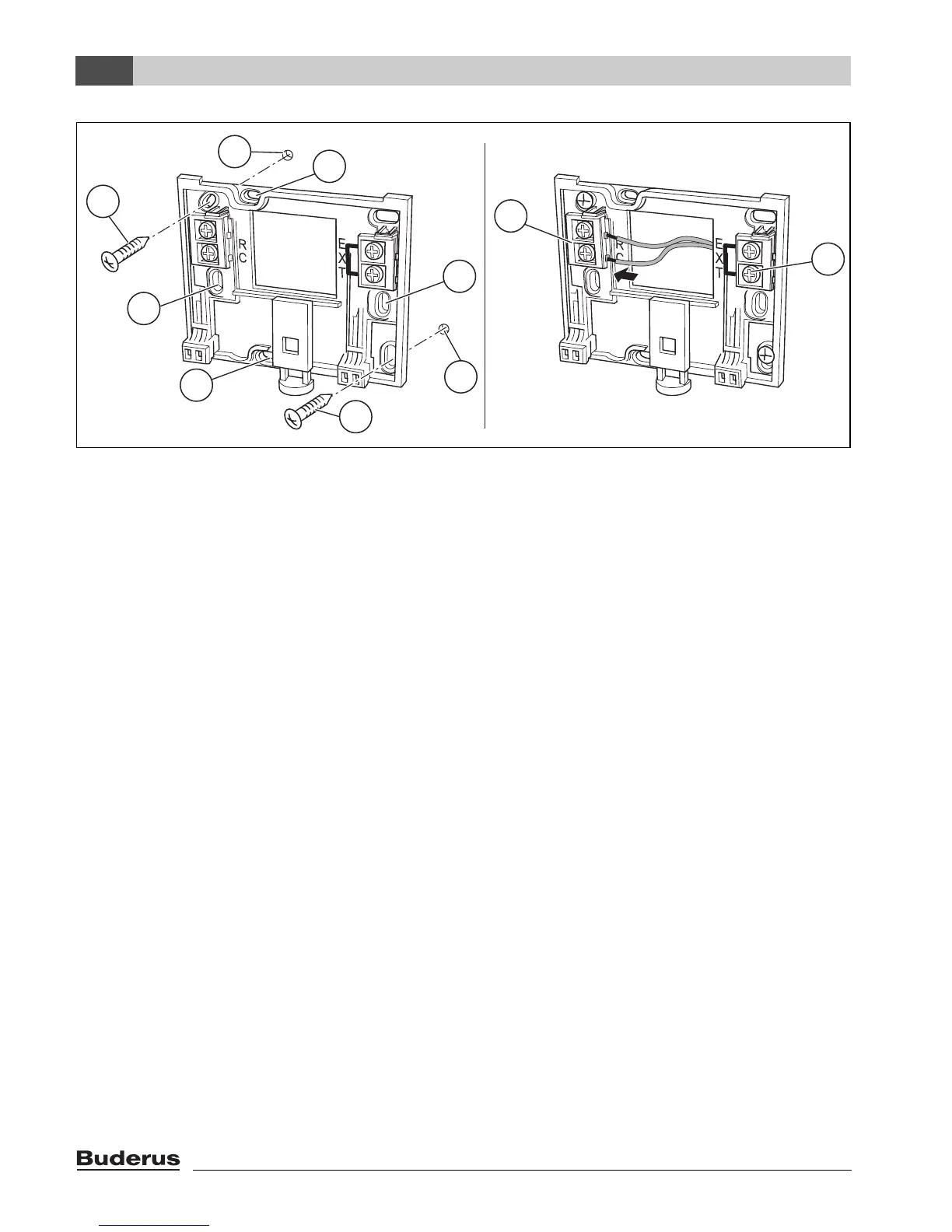
Fig. 3 Mounting the wall mounting base (left) and connecting the wires (right)
1 Hole drilled in the wall
2 Screws (included with the unit) for surface-mounting on the wall
3 Vertical mounting holes for mounting on a flush box
4 Horizontal mounting holes for mounting on a flush box
5 “RC” connection to the EMS (boiler)
6 “EXT” terminals for external room temperature sensor or for jumper
B If the RC35 programming unit is operated without external room temperature sensor, a jumper is
required at the “EXT” cable terminals [6] (condition as supplied from the factory).
B If the RC35 programming unit operates together with an external room temperature sensor,
remove the factory-fitted jumper at “EXT” and connect the external room temperature sensor in
its place.
6 720 618 477-03.1RS
2
2
3
3
4
4
5
6
1
1