Service Manual 04/2010 Rev.B
65
Mount the rotation switches on their support
and tighten handily the nuts
With pedals in rest position, leave 5mm of
clearance between them and the switches
(Fig.97).
Fig.97
Press the pedals all way down: they do not
have contact with the switches bodies. In case
of contact increase the previous 5mm
clearance (Fig.98)
Fig.98
Tighten the nuts FIRMLY.
Connect by using tape, the wires 4,5,6,7 and
the 4 commons ones all together connected,
to the steel wire coming from the 8 position
switch previously inserted. On King 5600R
connect the wires 12,13,17,18 and further 4
common wires to the steel wire from 4
position switch.
Connect by using tape, the wires 2,3 and 2
commons all together connected, to the steel
wire coming from 2 position switch. On King
5600 connect wires 12,13 and two further
common wires to the steel wire from the
second 2 position switch.
Connect the rest of the wires to the third steel
wire.
Pull up all steel wires simultaneously until to
get all wires out.
Remove the steel wires from the rest of the
wires.
Connect all wires to the switches.
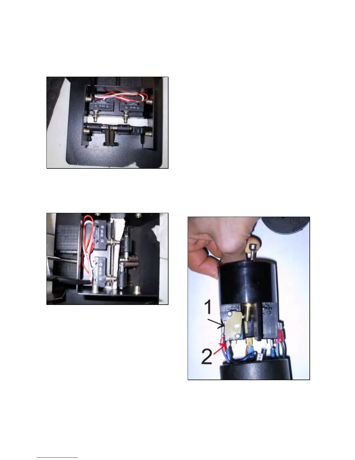
IMPORTANT: THE WIRES MUST BE FITTED
ON THE MICRO SWITCH IN OPPOSITE
POSITION COMPARED TO THE DRAWING
REPORTED ON 8 AND 2 POSITION SWITCH.
COMAND WIRES MUST BE FITTED ON PLUG
#1 WHILE THE COMMON ONES MUST BE
FITTED ON MIDDLE PLUG #2 (Fig.99).
Make some turns of tape around the 8 and 4
position switches (Fig.62) in order to avoid
short circuit.
Install the cable strain relief in the bottom of
the portable control and tighten the ground
wire FIRMLY.
Fit the column to the base.
Fit 8,4 and 2 position switch and the
emergency switch.
IMPORTANT: WHEN REMOUNTING
COLUMN ON THE BASE BE CAREFUL
NOT TO CRUSH WIRES.
Fig.99
Check if the machine works fine.
If the machine start to work alone when
switching on, it means that command wire/s
is/are reversed with the common one/s. Verify
which is the movement, dismount the