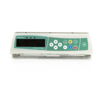
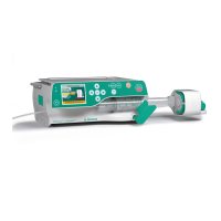
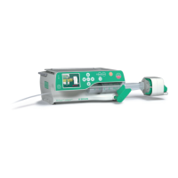
System Overview
1 - 2 Infusomat® Space 6.0
EN
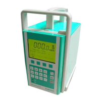
Physical Construction
The Infusomat® Space housing mainly consists of the bottom part,
the upper part, the front part and the operating device.
The battery module is inserted in the rear of the housing upper
p
art. The opening is covered by the battery compartment cover.
The operating unit is attached to the
front of the bottom part. The
thrust bearing of the tube pump (peristaltic pump), the spring-
mounted pressure elements for the two pressure sensors and the
air inline sensor as well as the shackle for the slide clamp of the
Infusomat® Space Line are located at the rear of the operating
unit. The operating unit is mechanically locked in its closed posi-
tion via three metal pins. A motor-driven lock bolt is used to lock
the operating unit. In case
of an emergency, the operating unit
can be opened through an opening on the left side of the housing
top. During normal operation this opening is closed with a plug.
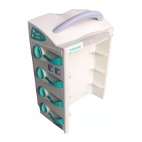
According to the line run the following subsystems are installed
in the housing front panel, from right to
left:
- Pressure sensor (upstream, container-side)
- Slide guide with 12 slides (mechanically coded,
can be dis-
mantled without tool)
Coding for ISPS: top left
Coding for ISPP: middle right
- Air inline sensor
- Pressure sensor (downstream, patient-side)
- Safety clamp (ISPS).
The slides are moved in the slide guide by
pump connecting rods.
The connecting rods are mounted on an eccentric shaft and are
led outside through a seal diaphragm. The complete pump is flex-
ibly mounted in the inner frame of the device and is moved in
co
mbination with the lock bolt. The lock bolt drive of the pump is
also installed in the inner frame.
The processor PCB with the external
connectors “P2” and “P3” is
located at the bottom of the housing bottom part.

 Loading...