Disassembly / Assembly
Infusomat® Space 6.0 3 - 43EN
1. Make sure that the following components are sufficiently lu-
bricated when installing the inner frame. If the
grease film is
not sufficient (stiff or jerky movements) grease these areas
slightly with Polylub GLY 501.
If chemical substances such as lubricating grease are used the
safety data sheets are to be observed
(see „Safety data sheets“ ➨
pg. 0 - 7).
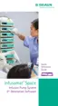
- Plastic guides (Fi
g.: 3 - 44 / Item 1) of the lock bolt
- Spring bearings and dovetail of the spring holder
(Fig.: 3 - 44 / Item 5)
- Guide (6 mm straight pin) of the pump frame at the bear-
ings (Fig.: 3 - 44 / Item 6)
- Toothed wheels (Fig.: 3 - 44 / Item 7) of the pump drive
- Movement areas (Fig.: 3 - 44 / Item 3) of the pump
frame
- Toothed wheels (Fig.: 3 - 44 / Item 4) of the lock bolt
drive
- Guides (Fig.: 3 - 44 / Item 8) and supporting area of the
lock bolt
2. Pay attention to the operating pin of the linear
potentiometer
when installing the lock bolt drive. The pin must engage in
the fork for the potentiometer when the spindle tappet is
clipped in.
3. Check all toothed wheels for damage after installation of the
lock bolt drive.
4. The spring holder of the pressu
re adjustment unit must run
smoothly with its dovetail guide in the guide of the pump
frame. Check smooth running without springs inserted before
final assembly.

 Loading...