Disassembly / Assembly
Infusomat® Space 6.0 3 - 25EN
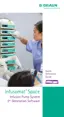
3.10 Inner frame
Designation Order No.
Lock bolt drive ISP . . . . . . . . . . . . . . . . . . . . . . . . . . . . . 3452 1429
Linear poti ISP . . . . . . . . . . . . . . . . . . . . . . . . . . . . . . . . 3452 1056
Pressure adjustment unit ISPS . . . . . . . . . . . . . . . . . . . 3452 1445
(spring holder, pressure springs, adjusting screw
adjusting nut, bracket, bracket locking)
Pump frame ISP, without motor . . . . . . . . . . . . . . . . . 3452 1402
Pump drive motor ISP . . . . . . . . . . . . . . . . . . . . . . . . . . 3452 1410
Lock bolt ISP . . . . . . . . . . . . . . . . . . . . . . . . . . . . . . . . . 3452 1496
Inner frame ISP . . . . . . . . . . . . . . . . . . . . . . . . . . . . . . . 3452 1437
Bracket locking and screws
(see „Service Parts and Screw Kit“ ➨ pg. 3 - 7)
Please pay attention to the corresponding notes during assembly
and installation (see „Inner Frame“ ➨ pg. 3 - 42).
Disassembly
1. Carefully press two bracket lockings (Fig.: 3 - 24 / Item 10) at
the front and rear out of
the inner frame (Fig.: 3 - 24 /
Item 3).
*
2. Push the bracket (Fig.: 3 - 24 / Item 6) forward against spring
tension, unhook from the inner frame and remove it together
w
ith the pressure adjustment unit (Fig.: 3 - 24 / Item 7).
3. Press the pump frame guide (6 mm straight pin) (Fi
g.: 3 - 24
/ Item 8) in longitudinal direction out of the linear bearings
of the pump frame and the inner frame holders and remove
the pump frame from the
inner frame.
*
Do not reuse the bracket lockings

 Loading...