Unit Elements
4
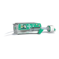
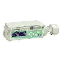
4- 14 Perfusor® compact, 2.1 gb
4.15 Drive Board
Designation Ord. No.
Drive board . . . . . . . . . . . . . . . . . . . . . . . . . . . . . . . . . . 3450 6691
with main PCB and satellite boards
for syringe size recognition
and recognition of direction of rotation
Exchange
1. Open unit (see "Open unit" ➨ p. 4 - 3).
2. Dismount drive (see "Drive" ➨ p. 4 - 12).
3. Disconnect zero force connector on the underside of the main
PCB.
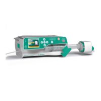
4. Loosen main PCB and the direction of rotation board.
5. Remove drive board.
6. Place new main PCB on aluminum profile and slide until
stopper of the aluminum profile from the motor side.
CAUTION
Cable layout according to figure.
7. Press board against stopper when screwing down. Tighten
screws hand-tight.
8. Fix satellite board.
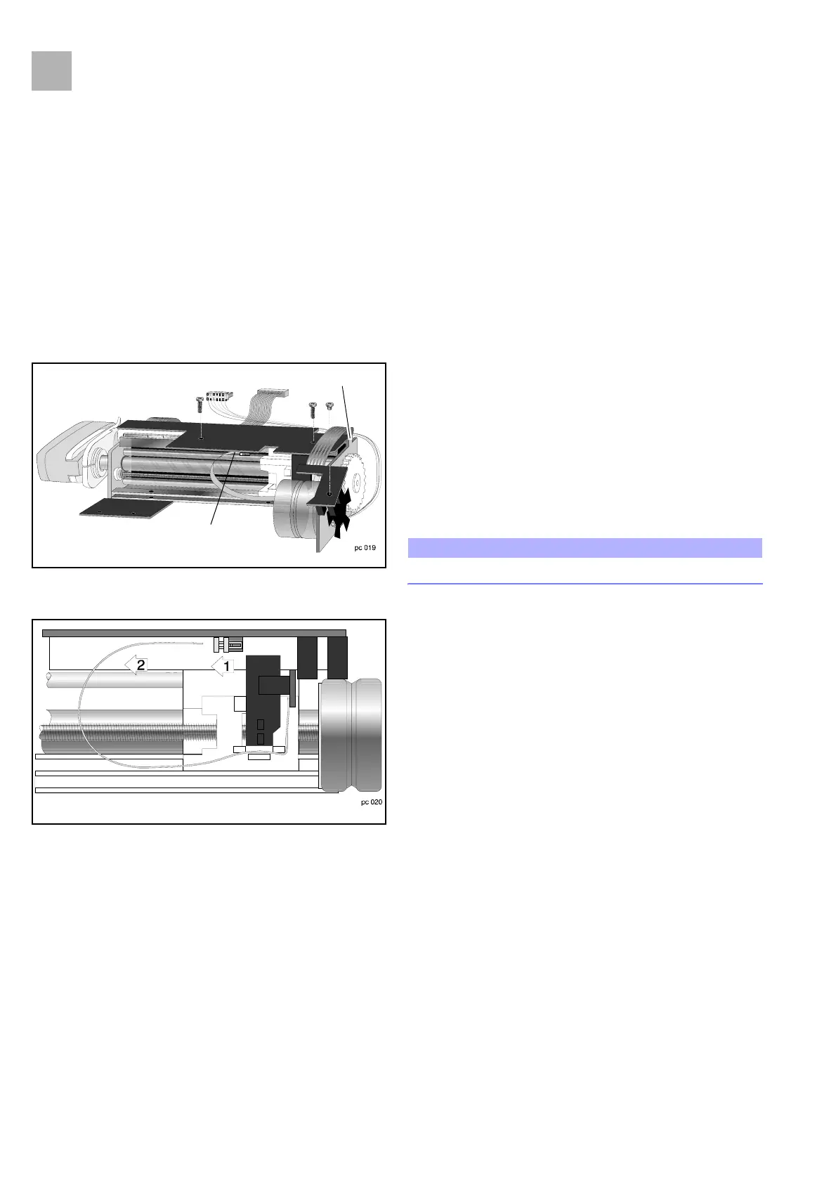
Cable layout please, see Fig.: 4 - 18. Lay motor cable under
direction-of-rotation board before fixing the board. Make
sure that the slotted disk can turn freely and smoothly.
9. Insert ribbon cable vertically in zero force connector and lock
connector with a screw driver. Position connector carefully:
the plug contacts can bend!
10. Assembly is done in reverse order. Do not squeeze the cable
(see "Close Unit" ➨ p. 4 - 4).
Fig.: 4 - 16
Zero force connector
Stopper
Fig.: 4 - 17
2.1