Classic Cycles Technical Resources
13
return spring before inserting the retaining
screw. The collar goes beneath the shift drum
stopper. Tighten the shift drum stopper pivot
screw securely.
14. Install the snap ring on the kick starter shaft.
15. Using a needle-nosed pliers, install the
crankshaft collar locating pin into the
crankshaft.
16. Install the crankshaft collar over the locating
pin.
17. Install the rotary disc valve after coating it
and the valve cavity liberally with oil.
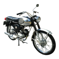
18. Carefully check the large "O" ring around the
outer perimeter of the rotary valve cover and
check the center oil seal to be certain that they
are in good condition. (Fig. 18) Install the
rotary valve cover and the 6 retaining screws.
19. Install the drive sprocket, sprocket washer
and retaining nut onto the transmission drive
shaft. Tighten the nut finger tight. Put the
sprocket stopper (special tool) in position and
tighten the retaining nut securely. Bend the
tabs of the washer against the flats of the
retaining nut to prevent its loosening while
the machine is being operated.
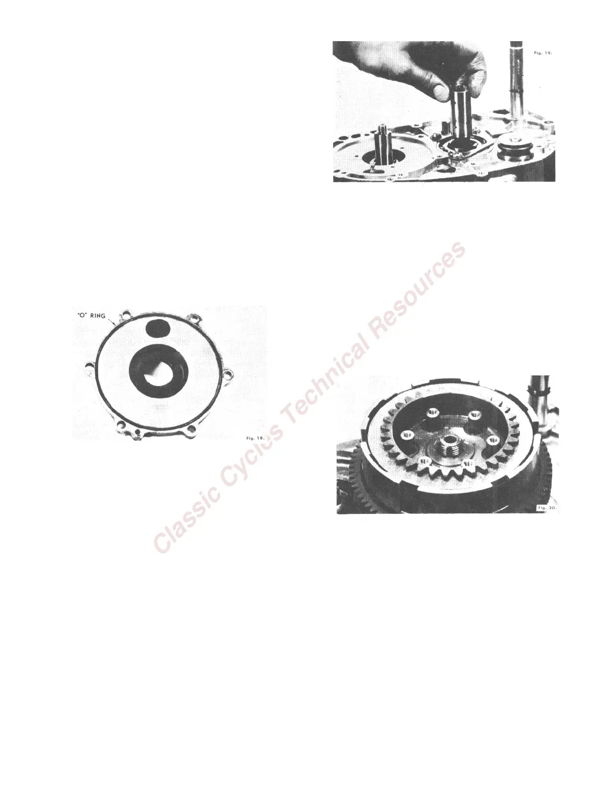
20. Install the clutch collar on the transmission
countershaft after oiling the collar liberally
and checking it for freedom of movement. (Fig.
19) NOTE: On newer models, the clutch collar
is built right into the shaft thereby eliminating
it as a separate component.
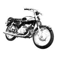
21. Install the clutch assembly onto the
countershaft and countershaft collar. Rotate
the clutch slowly while holding the sprocket
stationary in order to engage the drive dogs.
To positively engage the drive dogs, rotate the
kick starter shaft. When the clutch is properly
installed, approximately ½ inch of the
transmission countershaft will protrude
through the clutch assembly. (Fig. 20) NOTE:
On newer models, place the thrust spring over
the clutch drive gear, install the clutch
assembly, except for the clutch bracket, onto
the countershaft, replace the splined washer,
and install the clutch bracket.
22. With the sprocket stopper in place, install the
clutch retaining washer and nut and tighten
the retaining nut securely on the 90cc engine.
Bend the tabs of the washer against the flats
of the nut to prevent rotation of this nut
during engine operation. On the 50 and 60cc
engines, install the clutch retaining spring
clip.
23. Install the kick starter return spring, spring
guide and spacer.
24. Install the pinion gear onto the crankshaft
with the undercut side of the gear facing up.
With the piston seat in place, tighten the
pinion gear retaining nut securely. Remember
that this is a left hand thread.