14
25. Install the 6 clutch springs and reinstall the
clutch thrust plate using the 6 thrust plate
bolts. Tighten them securely.
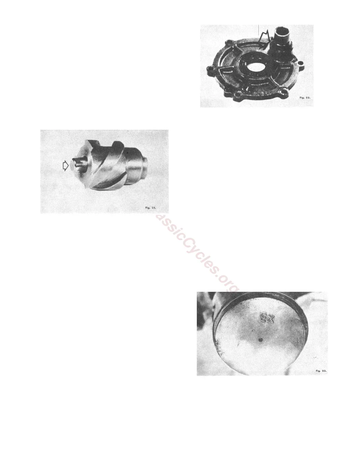
26. If the clutch release push screw has been
removed from the transmission cover, reinstall
it from the inside so that the flats of the
screws (as seen from the outside of the
transmission cover) are in a relatively
horizontal position with the back of the release
push screw flush with the inside of the
transmission case cover. (Fig. 3) Be certain
that the thrust bearing has been liberally
coated with grease and inserted into the push
screw. (Fig. 21)
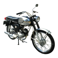
27. Position the transmission cover gasket on the
locating pins. Install the rubber "O" ring on
the carburetor inlet adapter, which is a part of
the rotary valve cover. (Fig. 22)
28. Install the transmission case cover by
securing all the transmission case cover
screws.
29. Turn the engine assembly over and install the
neutral light switch gasket and contact. With
the transmission in neutral gear, check to be
certain that the contact in the switch cover
touches the contact which is installed onto the
end of the shift drum shaft. Secure the cover.
30. Position the magneto armature plate making
use of the reference marks which you made
prior to removing this assembly. (Fig. 8)
Secure the plate with the 3 armature plate
screws.
31. Reattach the neutral gear switch wire to the
switch cover. Tighten the wire retaining
screw. (Fig. 7)
32. Install the flywheel onto the crankshaft and,
holding the flywheel stationary with the
stopper wrench, tighten the flywheel retaining
nut securely.
33. Install the piston pin onto the connecting rod
to check for fit. It should be snug but rotate
easily. Replace the pin and bushing if
necessary. Oil the bushing thoroughly before
installing the piston pin and piston.
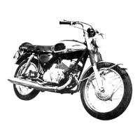
34. Install the piston pin and piston. When
installing the piston, the letters "EX" are to
face the exhaust port (front) on the cylinder. It
is important to position the piston this way
since the piston pin hole is slightly off center
for improved performance. If the piston is
installed backwards, a loud knocking sound
will be heard at low speeds. (Fig. 23)
35. Install the piston pin retaining clips.
36. Check to see that the piston rings are properly
installed. The chrome plated ring is the upper
ring and the cast iron ring is the lower ring.
The rings are to be positioned on the piston so