21
Communication Connections
Connect the applicable communication leads to the
automatic transfer switch as shown in the table below.
Pin
Number
Description Wire Type Connect To Notes
1 Normally Open
18 AWG [1 mm
2
] twisted pair conductors no longer than
61 m, 300V, 90
o
C copper wire
For Optional Alarm
2 Common
18 AWG [1 mm
2
] twisted pair conductors no longer than
61 m, 300V, 90
o
C copper wire
For Optional Alarm
3 Normally Closed
18 AWG [1 mm
2
] twisted pair conductors no longer than
61 m, 300V, 90
o
C copper wire
For Optional Alarm
4
Transfer Switch
Communication
18 AWG [1 mm
2
] twisted pair conductors no longer than
61 m, 300V, 90
o
C copper wire
4 (T/R) on transfer
switch board
Must Connect
5
Transfer Switch
Communication
Ground
18 AWG [1 mm
2
] twisted pair conductors no longer than
61 m, 300V, 90
o
C copper wire
5 (GND) Ground on
transfer switch board
Must Connect
6 +LED
18 AWG [1 mm
2
] twisted pair conductors no longer than
61 m, 300V, 90
o
C copper wire
Red wire on fault
indicator plate
For Optional Fault
Indication
7 Ground
18 AWG [1 mm
2
] twisted pair conductors no longer than
61 m, 300V, 90
o
C copper wire
Black wire on fault
indicator plate
For Optional Fault
Indication Ground
8 Not Used N/A N/A N/A
25 Utility 14 AWG [2.5 mm
2
] minimum 300V wire
Transfer Switch
Utility
Must Connect
26 Utility 14 AWG [2.5 mm
2
] minimum 300V wire
Transfer Switch
Utility
Must Connect
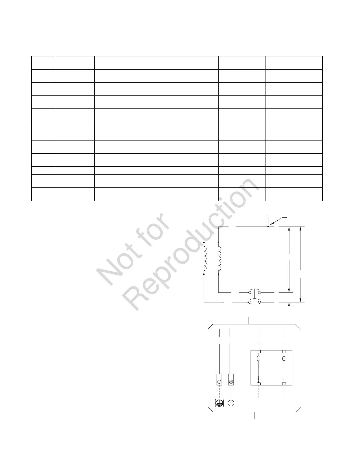
Generator AC Connection System
A single-phase, three-wire AC connection system is
used in the standby generator. The stator assembly
consists of a pair of stationary windings with two leads
brought out of each winding. The junction of leads 22
and 33 forms the neutral lead, as shown schematically
and as a wiring diagram. A complete schematic and
wiring diagram can be found later in this manual.
NOTICE
Neutral is not bonded to ground at generator.
NOTICE Generator must be used with only an UL
approved transfer switch that is compatible with the
generator.
Power Winding
Circuit
Breaker
Neutral
To Transfer Switch
Circuit
Break
er
From Alternator Power Windings
N
240V
120V
120V
33
22
11
44
0
22
11
44
L1
L2
 Loading...