23
System Control Panel
The generator control panel, located inside the
generator housing, is shown below.
Brief descriptions of the controls used during
installation are:
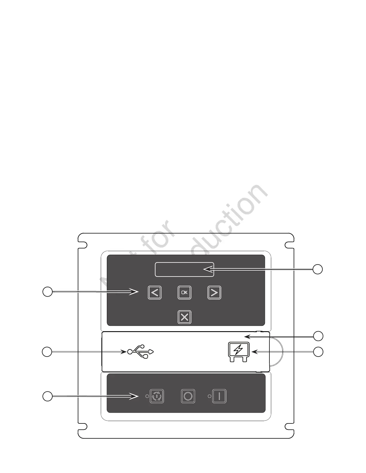
The generator control board, located inside the
generator, under the roof, is shown below. Brief
descriptions of the controls used during installation are:
A - Menu/Programming Navigation Buttons — See
Menu section for details
B - Mini USB Port — Authorized Dealer Service Use
Only
C - Generator Operation Control Buttons —
•“AUTO” Normal operating position. Press and
hold button to put unit into Automatic mode. If
an utility power outage is sensed, the system
will start the generator. When utility power is
restored, auto lets the engine stabilize internal
temperatures, shuts o the generator, and waits
for the next utility outage.
•“OFF” Turns o running generator, prevents unit
from starting, and resets any detected faults.
OFF must be pressed and held for more than 5
seconds in order to reset service codes.
•“MANUAL” Used to manually start the generator.
“AUTO” LED — LED will light when unit is placed
into Auto mode. LED will blink if exercise cycle is
not set or set to OFF.
D – 15 Amp Fuse — Protects the standby generator
DC control circuits. If the fuse has ‘blown’ (melted
open) or was removed, the engine cannot crank
or start. Replace the fuse using only an identical
ATO 15A fuse. One spare fuse is supplied with
the unit.
E - Cover — This protective cover must be opened to
access the fuse and the USB port.
F - Digital Display — Displays generator mode,
menu options, service codes, and service engine
indicators
More information may be found in Controls in the
operator’s manual.
MENU
ESC
AUTO OFF
MANUAL
A
B
C
F
E
D
 Loading...