20
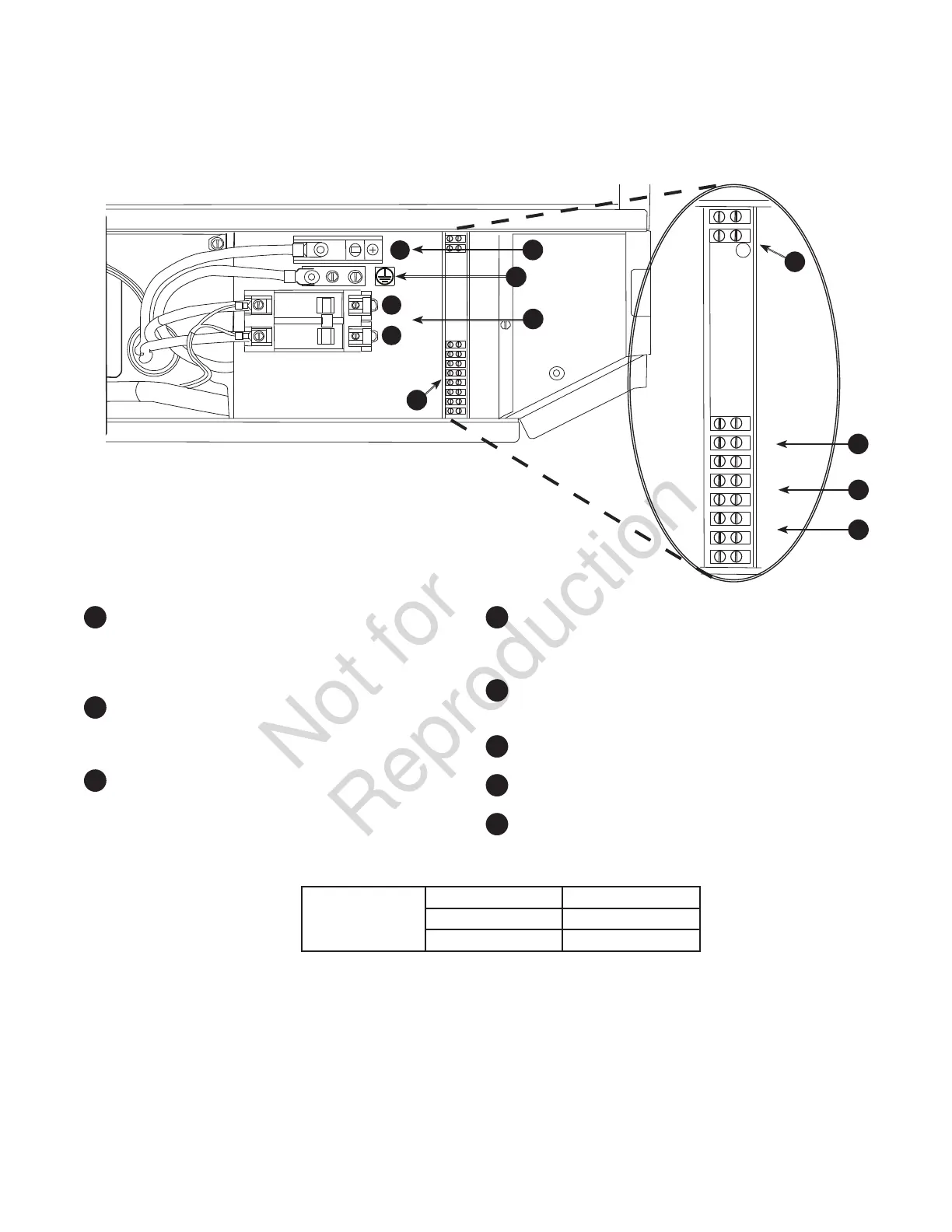
System Connectors
Low Voltage connections to signal fault contacts, transfer switch communication and auxiliary 12VDC power are
made via a field connection terminal block in control board area. Compare this illustration with your generator to
familiarize yourself with the location of these connections.
• For power output connection (Line 1, Line 2, Neutral, and Ground), refer to the following table:
17 kW 20 kW
4AWG [21 mm
2
] Cu 4AWG [21 mm
2
] Cu
3AWG [27 mm
2
] Al 2AWG [34 mm
2
] Al
• Reference NEC 2014 table 310.15 (B) (16) • Use National Electric Code for correction factors and wire size calculations
• Metric system rounded for simplicity.
• For transfer switch communication use #18 AWG [1 mm
2
] twisted pair conductors, no greater than 200 ft in length, 300
volt 90°C wire.
• When connecting to the terminal block, fasten only one wire to each connector screw.
• Torque terminal block screws to 4.4 in-lb [0.49 Newton meter].
• Torque circuit breaker connections to 45 in-lb [5 Newton meter].
A
- Two Pin Terminal Block — Used to connect
utility 240 VAC from fuse block in ATS to the
control board. Connect only one wire per
terminal. Use #14 AWG [2.5 mm
2
] minimum 300
volt wire.
B
- Fault Contacts — Use NO, COM and NC to
hook up a siren, light, etc. to alert you in case of
a fault. Contacts reverse state (NO goes to NC
and vice versa) upon a fault condition.
C
– Transfer Switch Communication (TxRx
and TxRx GND) — Connect to transfer switch
control board for communication interface using
18AWG [1 mm
2
] twisted pair wire.
D
– +LED and GND Connection — Not required for
wireless monitor included with unit. Available for
optional hardwired remote system status panel
accessory, #6154.
E
- Eight Pin Terminal Block — Used to connect
signal wires to the control board. Connect only
one wire per terminal.
F
- Power Connection (Line 1 and Line 2) —
Power connection to transfer switch.
G
- Ground Connection — Connect to transfer
switch ground
H
- Neutral Connection — Connect to transfer
switch neutral
25
26
1
2
3
4
5
6
7
8
]
]
]
]
L1
N
L2
B
C
F
H
G
D
A
E
 Loading...