EasyManuals Logo

Briggs & Stratton Fortress User Manual

Briggs & Stratton Fortress
156 pages
To Next Page IconTo Next Page
To Previous Page IconTo Previous Page
Page #13 background imageLoading...
Page #13 background image
Not for
Reproduction
13
Electrical and Fuel Inlet Locations
The 3/4 inch N.P.T. fuel inlet connector (A) and
electrical inlet location (B) is shown below.
A ½ inch knock-out is provided for the electrical
inlet. This inlet may be enlarged or supplemented to
accommodate a maximum conduit size of 1 ½ inches.
Ensure that the installed conduit(s) enter the unit in the
zone (C) shown in the drawing such that they properly
enter the electrical box and do not interfere with the
fully opened roof.
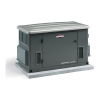
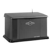
The standby generator is supplied with a base that,
unless mandated by local code, does not require a
concrete slab.
A
B
C

Table of Contents

Questions and Answers:

Question and Answer IconNeed help?

Do you have a question about the Briggs & Stratton Fortress and is the answer not in the manual?

Briggs & Stratton Fortress Specifications

General IconGeneral
Voltage120/240V
Frequency60 Hz
Fuel TypeGasoline
Wheel KitIncluded
Outlets(2) 120V 20A Outlets, (1) 120/240V 30A Locking Outlet

Related product manuals