2-2
GF Series
Installation and Operation Manual
X-TMF-GF Series-MFC-eng
Part Number: 541B137AAG
March, 2010
Section 2 Product Descripton
2-3 Operating Principles
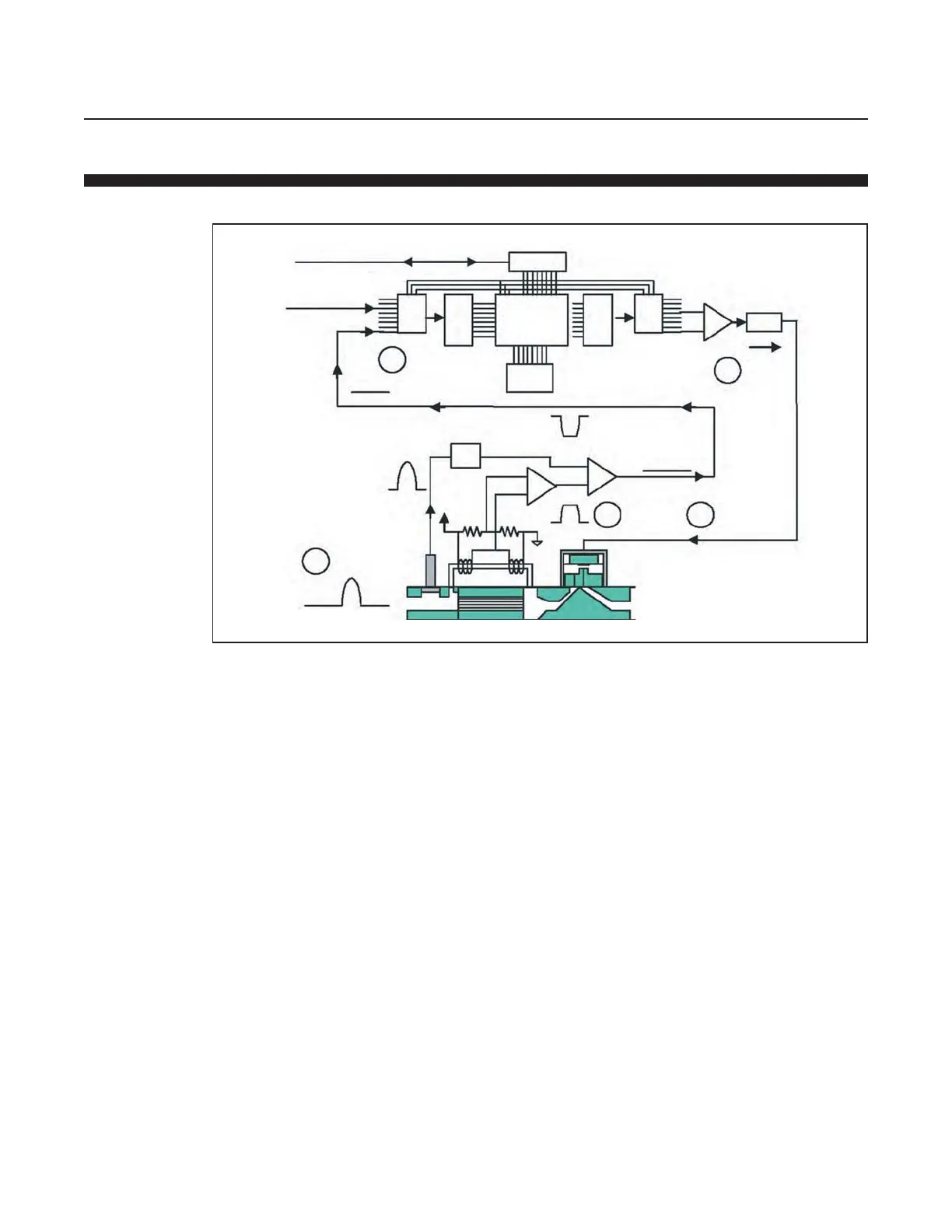
GF1XX operating principles are described in Figure 2-2.
Operating principles are listed below by following #1-5 in Figure 2-2.
1. The GF125 uses a pressure transducer and support circuitry that sums
the transducer signal in the sensor path (transducer not included in the
GF100 and the GF120). Incoming pressure fluctuation results in a
signal that is proportional to fluctuation.
2. The signal from the pressure transducer is inverted and then summed
in with the original sensor signal.
3. The two summed signals cancel each other out.
4. The sensor signal that is applied to the microprocessor is undisturbed.
5. The flow of process gas is undisturbed by incoming pressure
fluctuations.
Figure 2-2 GF1XX Operating Principles
Setpoint
Selector
(if Rs485 - analog
signal)
Setpoint
(if DeviceNet - serial data)
Indicated
Flow
Sensor
Simulator
Pressure
Transducer
1
Pressure
Fluctuation
PID Control
Valve
2
3
0
0
0
+
+
-
+
0
+
-
0
0
5
Flow
Valve
Selector
D/A
Microprocessor
Memory
A/D
DeviceNet
4
0

 Loading...

