3-5
GF Series
Installation and Operation Manual
X-TMF-GF Series-MFC-eng
Part Number: 541B137AAG
March, 2010
Section 3 Installation Instructions
3-6 Perform a Leak Test
WARNING
!
It is critical to leak test the gas supply lines and GF1XX connections before
turning on the process gas supply after any new installation. Check for
leaks using a helium leak detector or any other appropriate leak test
method. Follow leak test specifications as defined by integrator.
Figure 3-5 Mounting Screws Torque Pattern
5. If your GF1XX is configured with ¼" VCR fittings, secure the GF1XX
block to the gas panel with two, 8-32-UNC-2B" screws. Then connect
the inlet/ outlet fittings to the gas supply line using two wrenches.
Tighten the fittings to manufacturer recommendations.
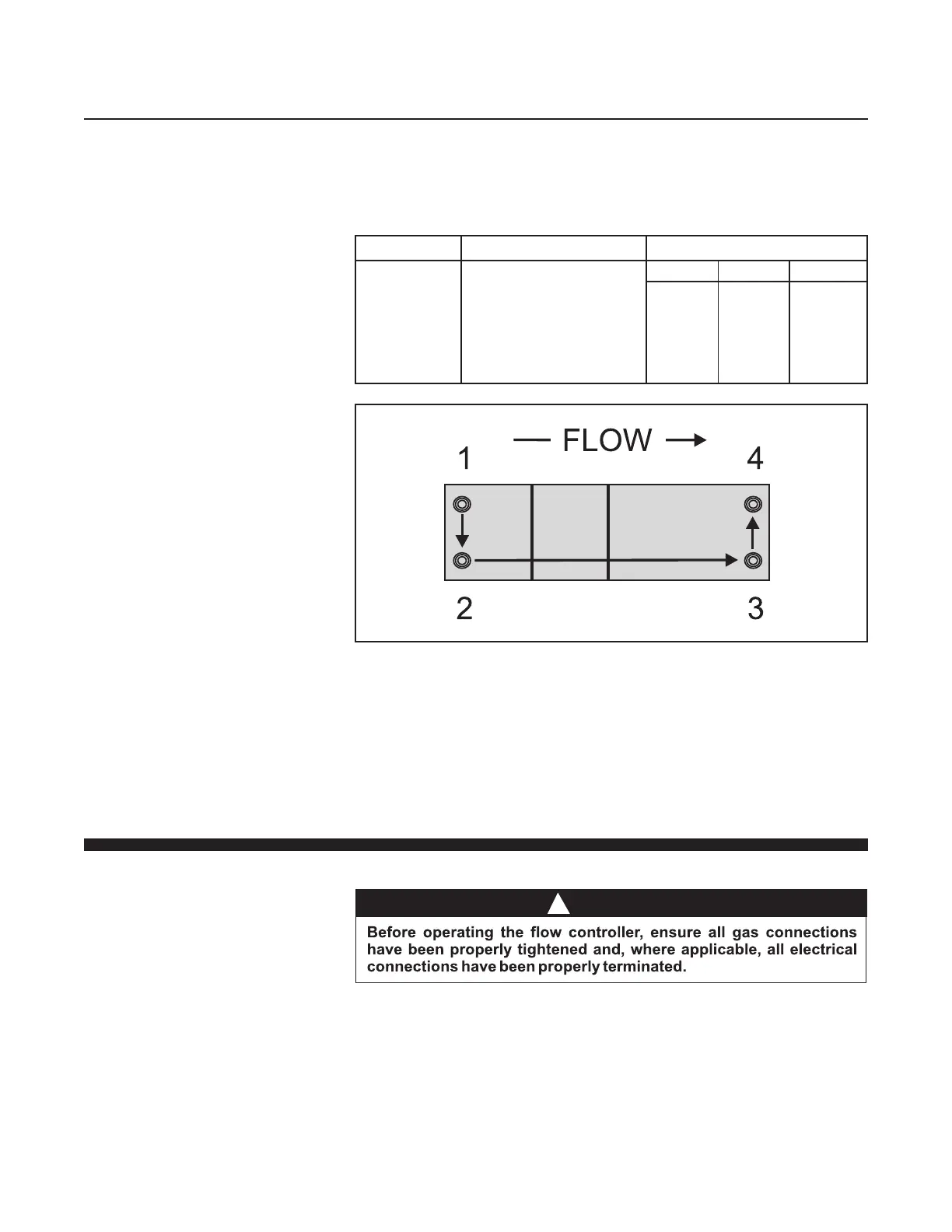
Table 3-2 K1 Substrate Torque Data
Connection
GF125 to
Subtstrate
Torque Pattern
Use a square pattern as
shown in Figure 3-5.
Start at 25 inch-pounds and
increase in increments of
10 inch-pounds until proper
value is obtained.
Torque (Inch-Pounds)
K1S K1R2 K1H
45 45 45
4. Using a torque wrench and a metric hex key, tighten the screws to the
torque value as described in Table 3-2 and Torque Pattern Figure 3-5.

 Loading...

