4-2
GF Series
Installation and Operation Manual
X-TMF-GF Series-MFC-eng
Part Number: 541B137AAG
March, 2010
Section 4 MultiFlo
®
Configurator
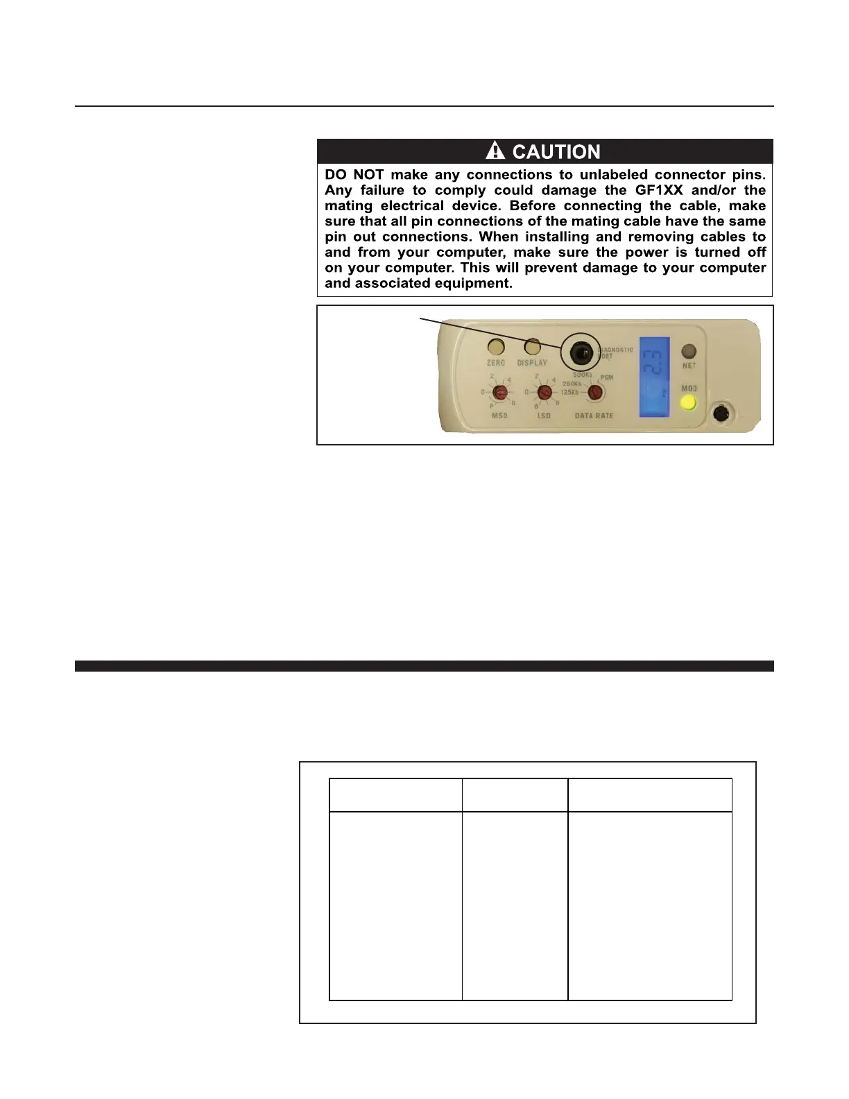
Figure 4-3 Diagnostic Port
Diagnostic Port
Connect the RS-485 end of the converter to the 9-Pin RS-485 end of the
MultiFlo Cable Adapter.
Connect the RS-232 end of the converter to the Serial Port of a laptop or
PC.
Download the MultiFlo Configurator software into your computer from the
Brooks Instrument website www.BrooksInstrument.com/Software.
Then install the MultiFlo Configurator as described in the MultiFlo
Configurator Software Manual.
4-3 Configure the Gas and Flow Range
Using the MultiFlo Configurator software, configure the gas and flow range.
Refer to Table 4-1 below. For field configuration software, contact your
local Brooks Service Center.
Table 4-1 Gas and Flow Ranges - MultiFlo Configurable - N2 Equivalent
Standard MG-MR Bin
Configurations
Flow range
Code
Gas Flow Range
(N2 Equivalent)
SH40
SH41
SH42
SH43
SH44
SH45
SH46
SH47
SH48
SH49
SH50
010C
030C
092C
280C
860C
2.6L
7.2L
015L
030L
040L
055L
3-10 sccm
11-30 sccm
31-92 sccm
93-280 sccm
281-860 sccm
861-2600 sccm
2601-7200 sccm
7201-15000 sccm
15001-30000 sccm
30001-40000 sccm
40001-55000 sccm