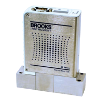
8-1
GF Series
Installation and Operation Manual
X-TMF-GF Series-MFC-eng
Part Number: 541B137AAG
March, 2010
Section 8 Removal and Return Instructions
8-1 Introduction
The following removal and return instructions are designed to minimize or
eliminate contamination normally associated with the most highly reactive
gases. Brooks has designed these instructions to reduce the overall
exposure to foreign particles.
8-2 Purge Gas Lines Before Removing the GF1XX
Refer to Section 3 for purging instructions.
8-3 Remove and Replace GF1XX
Perform the following steps:
1. Remove the GF1XX connections.
2. Immediately hard cap the inlet and outlet fittings on the GF1XX.
3. While in the production area, insert the old GF1XX into a plastic bag
and seal the bag. Keep the replacement GF1XX within the sealed bag
until just prior to installation.
4. Ensure new seals are in place for downported fittings. Refer to Section
3 for details.
5. Inspect the upstream and downstream gas lines and the GF1XX inlet
and outlet fittings for signs of contamination and damage.
6. Remove the new GF1XX from sealed bag, install the GF1XX and
retighten gas panel components. Refer to Section 3 for installation
details.
7. Once the GF1XX is installed, set the GF1XX to the purge state and
cycle purge the gas line with nitrogen or argon to remove any moisture,
oxygen, and contaminates. Refer to Section 3 for purging instructions.
8. Test for leaks at the GF1XX and at surrounding fittings.
9. Refill the gas line with process gas.
10.Warm up the GF1XX for ~30 minutes. Additional warm up time may be
required in order to stabilize the GF1XX in its new environment. Monitor
the zero drift and exercise it on and off with different setpoints.

 Loading...