D-4
GF Series
Installation and Operation Manual
X-TMF-GF Series-MFC-eng
Part Number: 541B137AAG
March, 2010
Section D Mics. Drawings
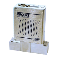
Figure D-6 DB9 to Card Edge Cable Adapter Assembly
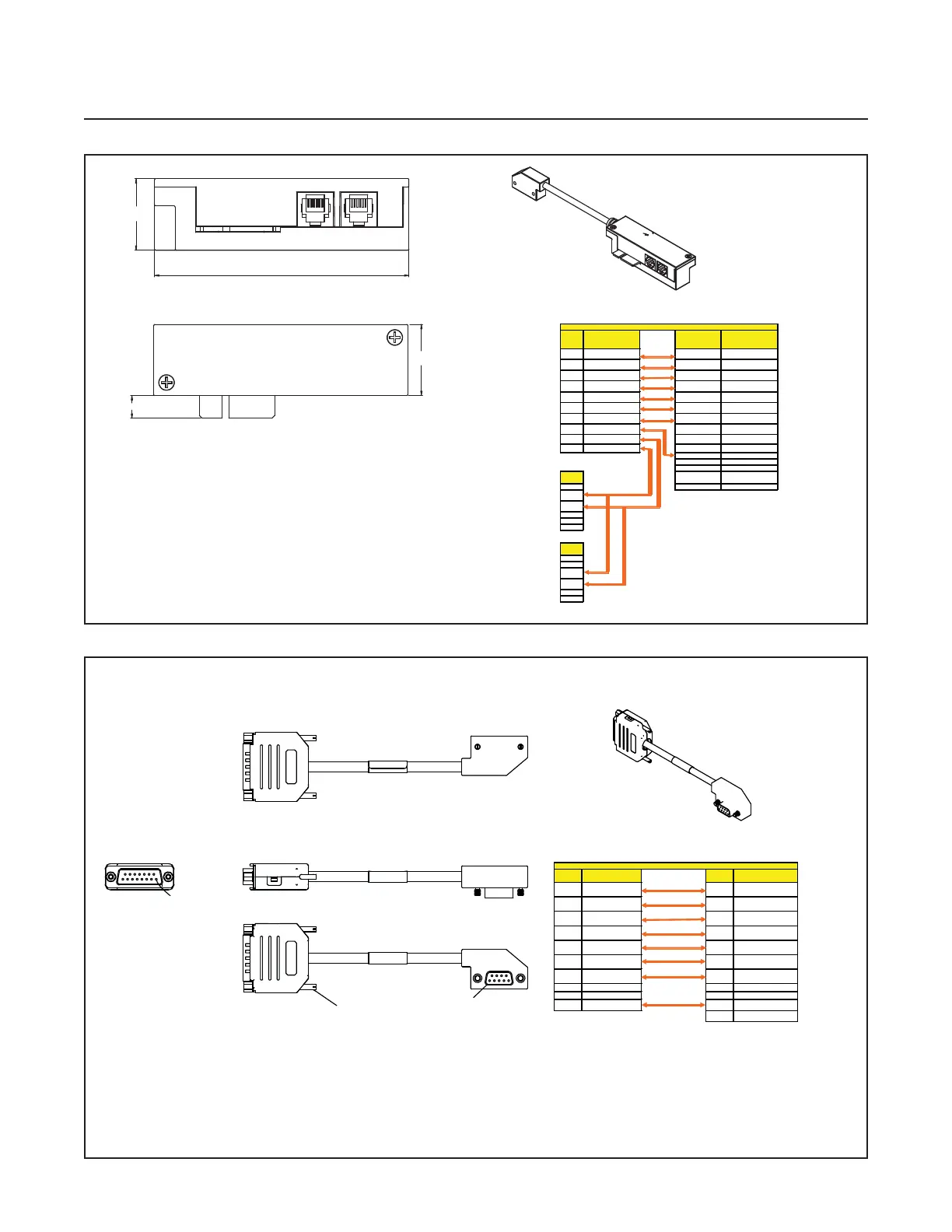
Figure D-7 DB9 to DB15, UDU15 Cable Adapter Assembly
P1
15-PIN MALE DSUB
PIN 1
P1
15-PIN MALE DSUB
PIN 1
2 X 4-40 UNC
JACK SCREWS
Note: Dimensions for cable length in Figure D-4
are applicable to this assembly
2 OUTPUT ( 0-5 VDC) 6 OUTPUT ( 0-5 VDC)
3 + 15 VDC 4 + 15 VDC
4 POWER COMMON 7 POWER COMMON
5 - 15 VDC 11 - 15 VDC
6 SETPOINT ( 0-5 VDC ) 15 SETPOINT ( 0-5 VDC )
7 SIGNAL COMMON 1,13,14 SIGNAL COMMON
8RS-485 (DX+) 2
9 RS-485 (DX-) 12 VALVE TEST POINT
Pin-Out for DB9 to DB15, UDU15
Cable Assembly PN: 7003071
1.04
3.71
1.04
0.33
Note: Dimensions for cable length in Figure D-4
are applicable to this assembly
Note: Measurements are in inches
MFC 20-pin Edge Card
with RS-485 Signals
2 OUTPUT ( 0-5 VDC) 3 OUTPUT ( 0-5 VDC)
3 + 15 VDC 4 + 15 VDC
4 POWER COMMON 2 POWER COMMON
5 - 15 VDC F - 15 VDC
6 SETPOINT ( 0-5 VDC ) A SETPOINT ( 0-5 VDC )
7 SIGNAL COMMON B,C,10 SIGNAL COMMON
DRAIN WIRE 8 RS-485 (DX+)
8 RS-485 (DX+) 9 RS-485 (DX-)
9 RS-485 (DX-) 6
Cable Assembly PN: 7003083
Pin-Out for DB9 to Card Edge (Corresponds to Connector Option "EX")