Polycold Cryochiller Installation
Installation and Operation Manual Evacuate the Refrigerant Line and Cryosurface
Brooks Automation
214072 Revision B 4-33
2. Open both valves on the service manifold.
3. On the following valves, remove the solenoid coils and place coil magnets on the valve stems:
See Figure 4-25, Figure 4-26, and Figure 4-27.
• Single Circuit:
VLV5 in the cold valve box
VLV6 in the warm valve assembly.
• Dual Circuit:
VLV5, VLV11 in the cold valve box
VLV6 and VLV12 in the warm valve assembly.
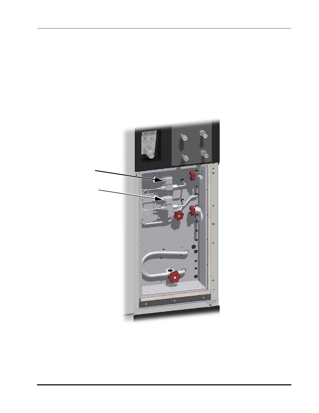
Figure 4-25: Cold Valve Box
VLV5
Cool Ckt 1
VLV11
Cool Ckt 2