Installation Polycold Cryochiller
Connect the Refrigerant Line Thermocouples (Type T) Installation and Operation Manual
Brooks Automation
4-38 214072 Revision B
4. On the refrigerant line, locate the thermocouple wires labeled COIL IN and COIL OUT.
a. Fold a small piece of tape around each thermocouple wire next to its label.
b. Label the tape “Circuit 1” on the COIL IN and COIL OUT thermocouple wires coming from
the first refrigerant circuit.
c. Label the tape “Circuit 2” on the COIL IN and COIL OUT thermocouple wires coming from
the second refrigerant circuit.
5. Strip about 1/4 inch (6 mm) of insulation from the end of each thermocouple wire.
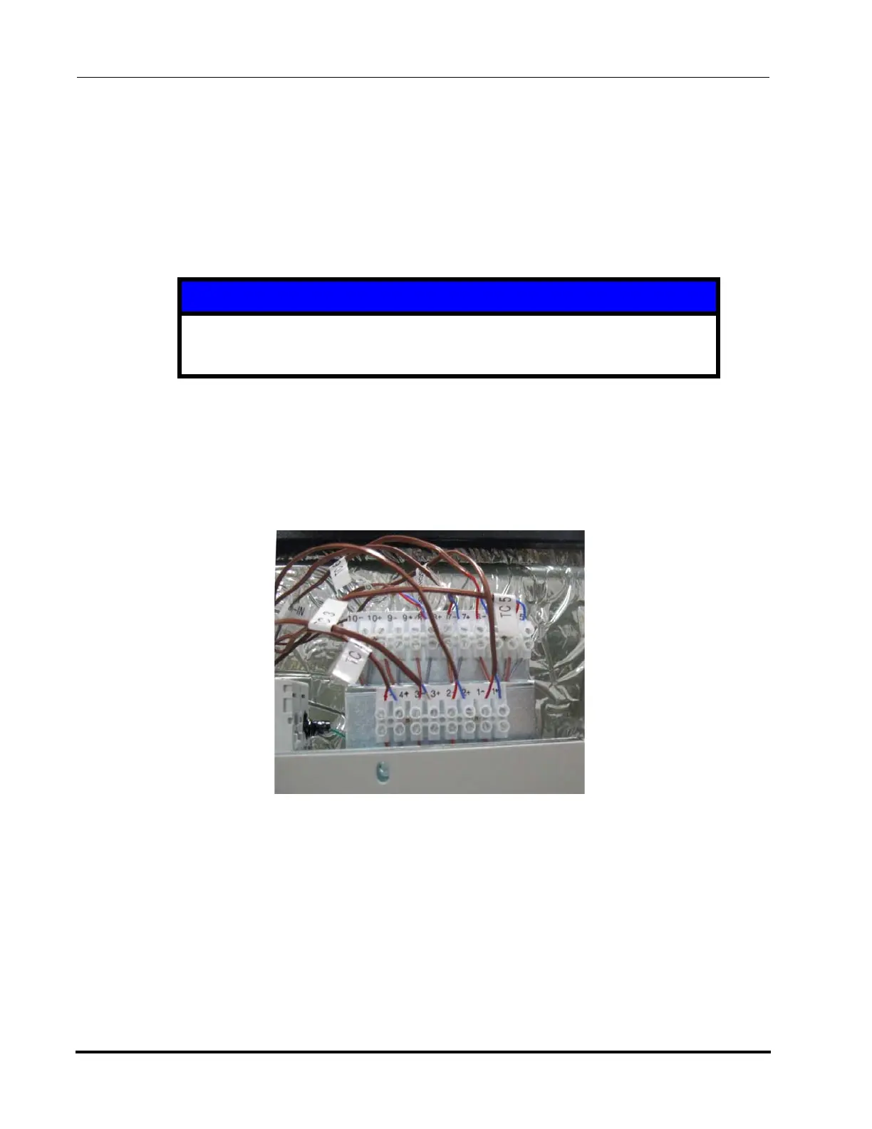
6. Attach the thermocouple wires to their designated locations. See Figure 4-30 and Table 4-3
• The blue-insulated copper wire must be attached to the positive (+) terminal.
• The red-insulated constantan wire must be attached to the negative (-) terminal
• Torque terminal screws to 0.34Nm (3 lb-in).
• Refer to the System Wiring Diagram provided with your system
7. Minimum recommended Thermocouple usage is Coil In and Coil Out for each refrigerant circuit.
Cool plates should also have a Thermocouple.
Additional Thermocouples can be added by the user as desired.
If you are working on a single circuit Polycold Cryochiller, connect the Thermocouple wires as fol-
lows:
• Position # 9: COIL IN
• Position # 10: COIL OUT
NOTICE
Do not nick the conductor. The wire may break at the nick from system vibration
and can result in damage to the equipment.
Figure 4-30: Thermocouple Terminal Block