11 | DEDisplay Remote // Display Central // About these original operating instructions
6 Explanation of the illustrations
Illustrations in these operating
instructions show functions by way of
example and may differ from the actual
appearance of your Brose Drive System.
All illustrations are schematic and
exemplary. The details of your e-bike
may vary depending on the e-bike
manufacturer. Detailed information
on your entire e-bike is available from
your specialist dealer and e-bike
manufacturer.
The numbering in the following tables
refers to the illustrations at the beginning
of this manual.
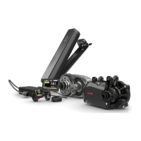
Overview illustrations
A. Quick start overview of the
Brose Display Remote E41227
control unit
B. Quick start overview of the
Brose Display Remote E41227
control unit with the
Brose Display Central E41229
display unit
C. Overview of key assignment for
the
Brose Display Remote E41227
control unit
D. Assembly and adjustment of the
Brose Display Remote E41227
control unit
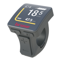
E. Overview of the Brose Display
Central E41229
display unit
F. Assembly and adjustment of the
Brose Display Central E41229
display unit
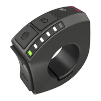
Components shown
(1) Button (On/Off)
› System on/off
(2) Button (Light)
› Jump one level back in the menu
(3) Button (Menu)
› Confirm selection
› In case of operation without the
Brose Display Central E41229
display unit, the button is
deactivated
(4) Button (Plus)
› Increasing the support level
› Scroll up in the menu
(5) Button (Minus)
› Reduce support level /
› Scroll down in the menu
(6) Button (push assist)
› Enable push assist
(7) View
› In case of operation with the
Brose Display Central E41229
display unit, the displays are
deactivated
(8) Display Remote connector
› Connection to the motor unit
(9) Grub screw
› Fastening of the control unit
(10) Brose Display Central E41229
display unit
(11) Screw (1x)
(12) Sleeve nut (1x)
(13) Retaining bracket (2x)
(14) Silicone adapter (2x)
(15) Screw (2x)
(16) Lock nut (2x)
(17) Display Central connector
› Connection to the motor unit