MAINTENANCE PROCEDURES
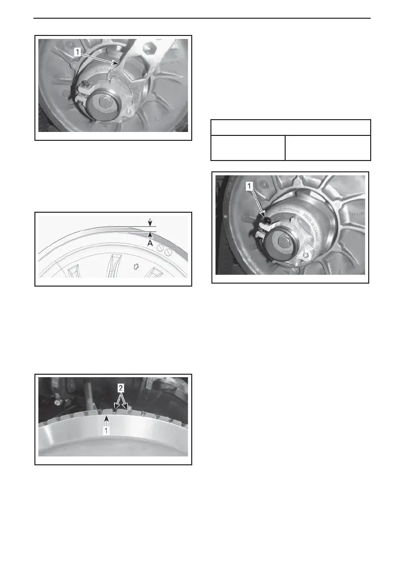
mmo2011-003-011_a
ADJUSTER HUB
1. Suspension adjustment tool
NOTE: The adjustment ring has left
hand treads.
Belt without External Cogs
mmr2009-081-001_a
PRELIMINARY SETTING
A. 0 mm to 2 mm (0 in to .08 in)
Repeat step 5 until the bottom of
grooves on the external side of drive
belt are flush with the driven pulley
edges.
mmr2008-040-108_a
PRELIMINARY SETTING
1. Driven pulley edge
2. External drive belt grooves
NOTE: Turning the ring counterclock-
wise low ers the belt in the pulley. Turn-
ing the ring clockwise raises the belt in
the pulley.
6. Tighten the clamping bolt to specifi-
cation.
TIGHTENING TORQUE
Clamping bolt
5.5 N•m ± 0.5 N•m
(49 lbf•in ±4lbf•in)
mmo2011-003-010_b
1. Clamping bolt
7. Install belt guard, refer to
DRIVE
BELT GUARD INSTALLATION
.
8. Close side panel, refer to
SIDE
PANELS
in
CONTROLS, INSTRU-
MENTS AND EQUIPMENT
.
NOTE: This setting is correct as a pre-
liminary adjustment for most models
and belt types. In some cases, when
starting the engine, the vehicle could
creep, indicating that the belt is too
tight.
If the vehicle creeps, lower the drive
belt height from the preliminary set-
ting. Repeat procedure until creeping
stops.
Reverse Activation
NOTE: The reverse may not activate
or may be harder to activate if the belt
is positioned too high in the driven pul-
ley. If reverse activation doe s not work
properly, ensure the drive belt is prop-
erly adjusted. Adjust the drive belt
lower in the driven pulley if needed.
114
______________