Measuring Ampifier Type 2525
User Manual Vol.1
3–5
BE1406–12
Chapter 3 –Operation Overview
Set-up and Measurement
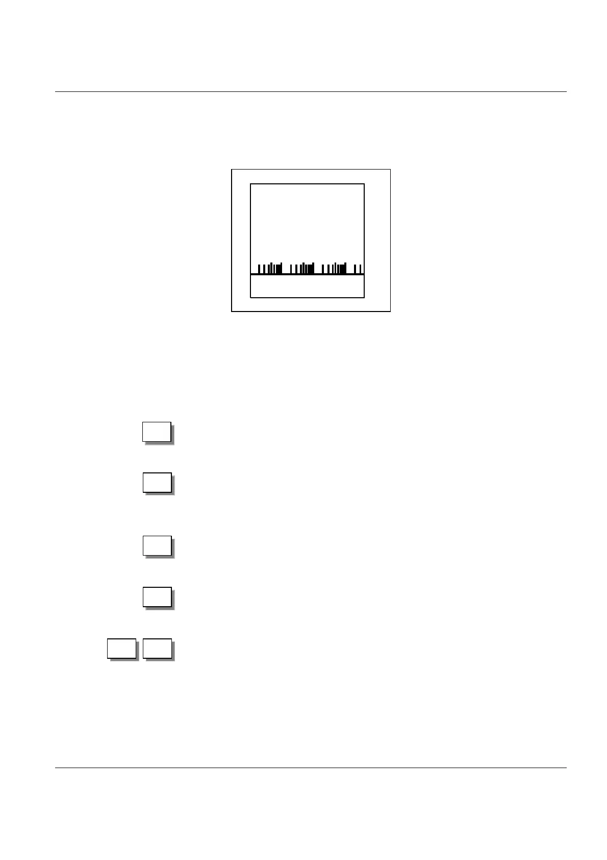
During measurement the screen is continuously updated to reflect the current
measurement output data as well as providing information regarding the current
set-up conditions. See Fig.3.3.
3.2.2 Using the Pushkeys
To operate the amplifier manually the six front panel pushkeys shown in Fig.2.1
are used. These pushkeys carry out the following functions:
For carrying out the selected measurement function as well as for show-
ing the selected measurement screen. During measurement it can be
used to reset the detectors.
In Set-up mode, allows you to select the option the arrow cursor is
pointing at. In Measurement mode (with Digits + Bar-graph or Large
Digits selected for Display Mode, see section 4.2.10), it stops the meas-
urement and returns to the Main Set-up menu.
Returns you to the previous menu.
Reserved for interface control. Returns the amplifier to manual control.
For moving the arrow cursor on the menus either up or down among
options, or, in cases where values are to be entered, allows you to in-
crease or decrease the value. Pressing continuously on the key causes it
to work like a “speeder”, allowing you to scroll through values very
quickly.
Every screen on the amplifier indicates which choices are available for selection or
specification of a set-up or measurement option/parameter. If an option/parameter
Fig.3.3 Screen during measurement
AC out:100 mV/ms
-2
Addressed
Mode: Acceleration
.
.
.
.
Upp. freq. lim 10 kHz
Low. freq. lim 0,1 Hz
Upp. 20dB
Remote
RMS
Ch. 1
0
100 pC 159 Hz Ref Off
Set-up: 1
110.1
Digits + bar graph
1
.
0
0
941378e
ms
-2
Meas
Setup
Retrn
Local

 Loading...


