Measuring Ampifier Type 2525
User Manual Vol.1
Brüel & Kjær
3–6
Chapter 3 –Operation Overview
Set-up and Measurement
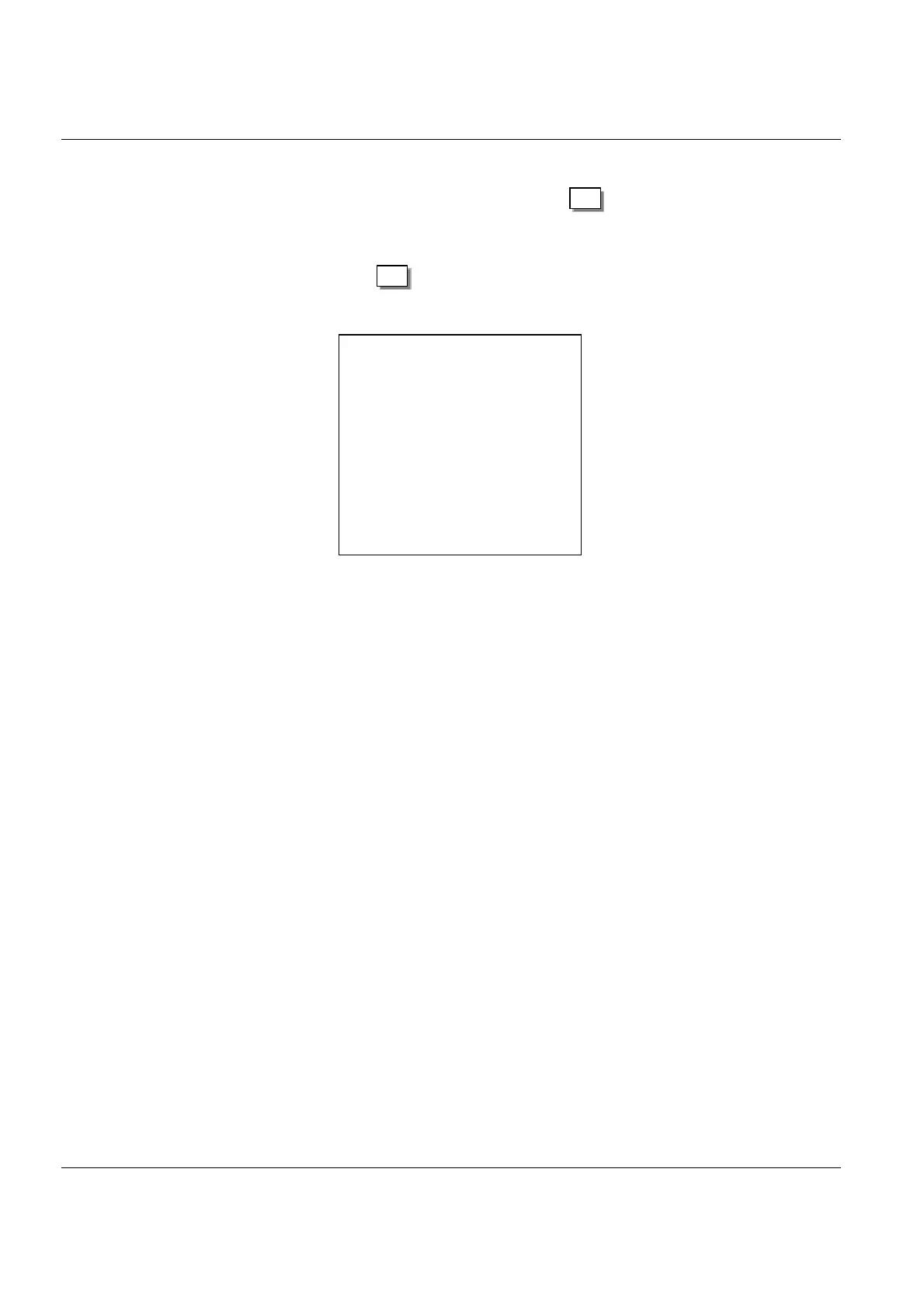
has been selected this will be indicated by a “*” to the left of the choice. A “>” to
the left of an option/parameter indicates that, if is pressed, this option/param-
eter will be selected.
For example, Fig.3.4 shows a screen in which the option Accelerometer has been
selected, but where, if is now pressed, Force Transducer will be selected in-
stead.
3.2.3 Using the Menus
The menus are described in detail in Chapters 4 and 5 of this manual, but can be
summarized as follows:
● Main Set-up
This is the general name for all the amplifier’s first level menu screens (see
section 4.2). Thus the Main Set-up includes both the menus which control the
display as well as the menus which control measurement. In addition, there are
a number of menus which are used to specify a range of non-measurement, non-
display parameters (such as resets, interface specifications, etc.).
● Display Set-up
While there is a single menu called Display Set-up, there are several menus
which fall under the general function of Display Set-up. The Display Set-up
menu is for selecting the calculation carried out on measurement data before it
is shown on the screen (RMS, +Peak, –Peak or Peak-to-Peak). The remaining
display set-up menus are used to control the way in which measurement data
appears on the screen, the units which appear by measurement values and, for
example, the back (LCD) lighting used.
● Measurement Set-up
This set of menus contains all the parameter selections available for setting the
amplifier for making a measurement. These menus are discussed in detail in
Chapter 5.
Fig.3.4 Example of how * and > are used to set up the amplifier
menus
Setup
Setup
941415e
Measurement mode
Channel: y
Acc. transducer
Acceleration
Velocity
Displacement
Force transducer
Force
(if alarm on and setup)
ALARM LEVEL CHANGED!
.
.
.
.
.
Remote Addressed
>
*

 Loading...


