Measuring Ampifier Type 2525
User Manual Vol.1
Brüel & Kjær
4–4
Chapter 4 –The Menus
Main Set-up
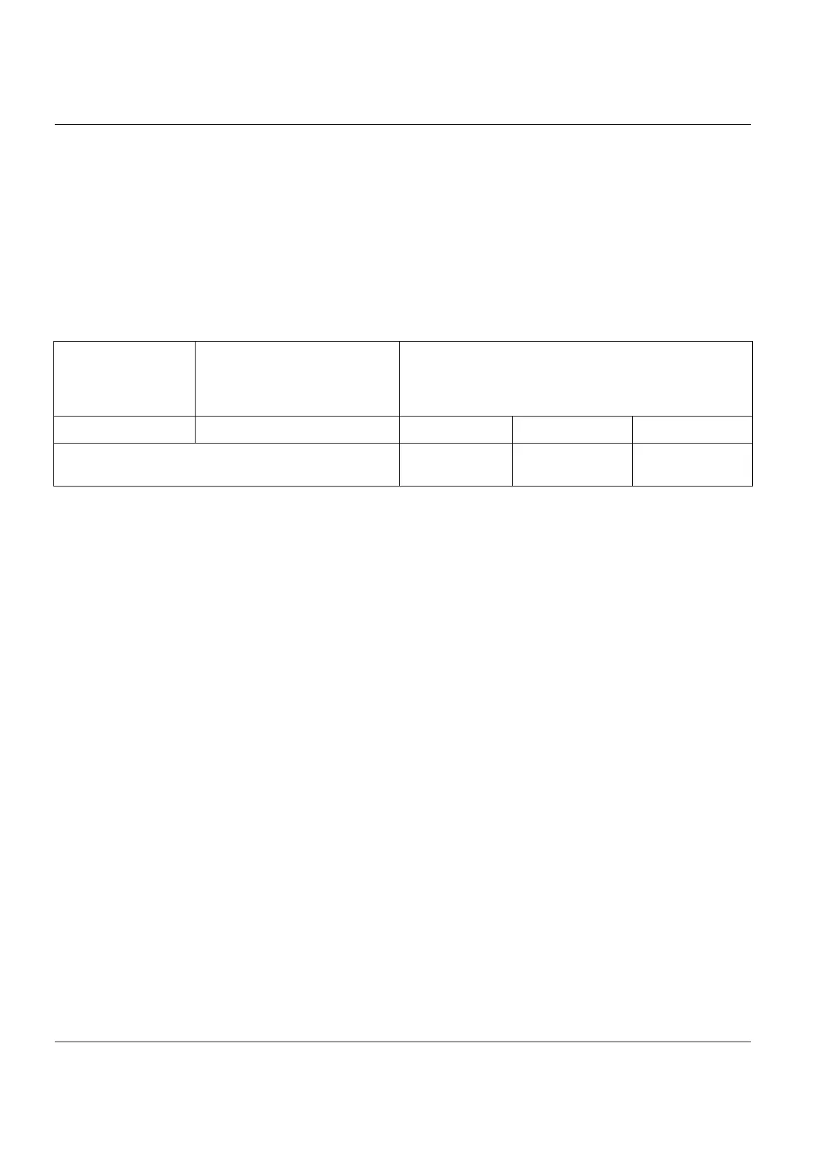
adjusted to produce a test voltage level of 1V rms at the Output sockets of the
amplifier. This is obtained with the amplifier acceleration mode control settings
specified in Table 4.1. With the velocity and displacement modes, the test voltage
output level is reduced to 100 and 1.0mV respectively, due to attenuation by the
integration stages of the amplifier.
To check the correct function of the 2525, a voltmeter or other indicating instru-
ment may be used to measure the test voltage. With the amplifier control settings
prescribed in Table 4.1, the test voltage output levels should be within ±2% of the
values specified.
To determine absolute levels with recorded measurements:
1. Record the measured signal from the output of the 2525.
2. Note the output sensitivity (S
p
) of the amplifier.
3. Without changing the input sensitivity of the recorder, adjust the amplifier as
prescribed in Table 4.1 and set the Reference Generator to ON to record the 1V
test signal, and then switch it OFF again. On playback the amplitude of the
recorded test signal will correspond to a reference level (L
r
)
.
The absolute level of the measurement can be determined by comparing the refer-
ence level to the recorded measurement.
For further information on determining absolute levels of tape recorded data, con-
sult the instruction manual of the recorder used.
4.2.5 Interface Set-up
This menu is for specifying the parameters for the IEEE–488 and serial interfaces.
Depending on which option you select, a new menu will open up for specifying the
relevant parameters:
For
Input gain = 20dB
Output gain = 0dB
mV/Unit read-out is
Transducer Sens.
conditioning setting
Output Reference Level
10 1.00 pC/ms
-2
1 V
RMS
100 mV
RMS
1 mV
RMS
Acc.–Vel.–Displ.-Force Measurement Mode Setting
(section 5.2)
Acceleration/
Force
Velocity Displacement
Table 4.1 Test voltage output levels available with different control settings on the 2525
L
r
1
S
p
-----
=

 Loading...


