Measuring Ampifier Type 2525
User Manual Vol.2
4–3
BE1394– 11
Chapter 4 – Syntax and Data Types
Formats for Interface Messages
Example:
:Channel_1:Measurement_Mode Acceleration;:Channel_1:Output_Gain 20<Te>
When interface messages are joined together using (;), the header path may be
omitted for a sequence of interface sub-headers belonging to the same header path
as shown in the following example:
:Channel_1:Measurement_Mode Acceleration;Output_Gain 20<Te>
Some main rules are:
● After a Program Message Terminator (<Te>) the parser recognizes only “root”
headers (this is also the case after Power Up).
● After reception of a compound header including a header path and a sub-header,
the parser assumes the same header path until it recognizes either a (:) or a
<Te>. This allows several sub-headers to be joined together with a (;) using only
header path in the first message as shown in the example above.
Messages from the Amplifier
The structure of the response messages returned by the amplifier depends on the
nature of the query from the controller. The messages are in minimum code (mne-
monics) or written in full – see section 4.1.4.
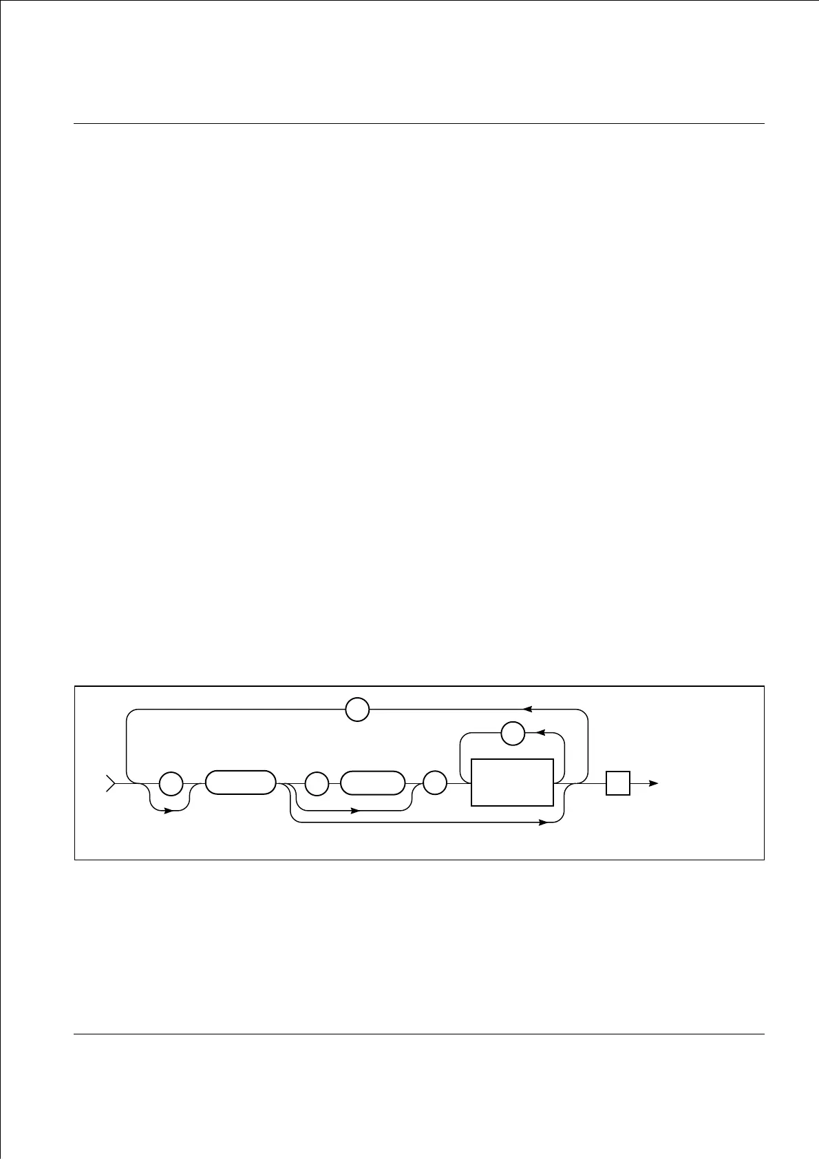
4.1.2 Use of Syntax Diagrams
In this manual, syntax diagrams are used to explain the individual messages. Syntax
diagrams use three types of symbols, as illustrated in Fig.4.1.
Rectangular symbols indicate that the enclosed data must be replaced by a data item
defined elsewhere or chosen by the user. The name of the data item is quoted in the
upper left-hand corner of the symbol. The type of the data item, and its allowed
length in parentheses are, where appropriate, given in the lower right-hand corner.
Circular symbols enclose single character literal data that must be included in the
Fig.4.1 General message syntax
941582e
ABCD_EFGH
Data can be bypassed
Te
: :
;
,
Data Field
x*
SP
—
IJKL_MNOP

 Loading...


