Electrical connections7
Logamax plus GB162-80 kW/100 kW - Subject to modifications resulting from technical improvements!36
z Connect the free connector of the EMS bus connecting
cable (fig. 38) to the first module (fig. 39).
z If more modules are used, the EMS bus connection for
the second module may be branched off from the first
module using the cable enclosed with the module (fig. 39
and 41).
7.2.2 Installing function modules outside the boiler
z Install the module on the wall according to the installation
instructions of the module.
z Make an EMS bus connection cable using a 2-core cable
and the connector enclosed with the module (fig. 40).
Important: Use the connector of the same color as the
connections on the module.
z Connect the EMS bus connection cable to the orange RC
connection of the external connection board (fig. 41,
pos.
1).
z To connect other modules see paragraph 7.2.1.
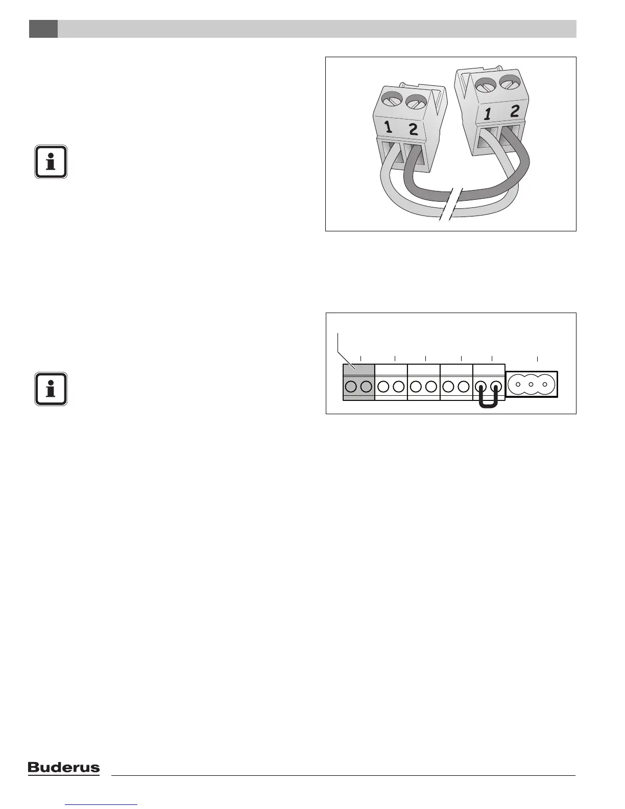
Fig. 40 EMS bus polarity
NOTICE
Pay attention to the polarity when using an EMS
bus connection cable.
z Connect the wire from terminal 1 to
terminal 1 and from terminal 2 to terminal 2
(fig. 39 and 41).
Fig. 41 External connection board - Room controller RC and
EMS bus (connection color orange)
RC
FA
WA
FW
EV
DWV
1
NOTICE
Pay attention to the polarity when using an EMS
bus connection cable.
z Connect the wire from terminal 1 to
terminal 1 and from terminal 2 to terminal 2
(fig. 39 and 41).