Electrical connections 7
Logamax plus GB162-80 kW/100 kW - Subject to modifications resulting from technical improvements! 37
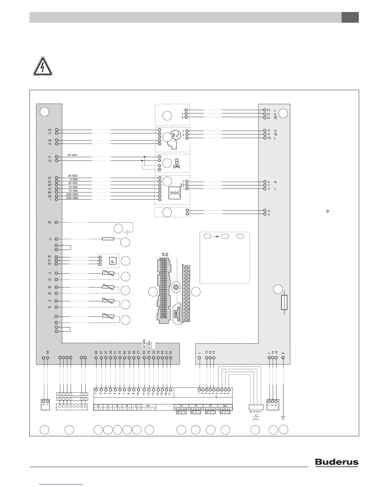
7.3 Electrical wiring diagram
Fig. 42 Electrical wiring diagram
CAUTION
Label all wires prior to disconnection when servicing. Wiring errors can cause improper and dangerous
operation. Verify proper operation after servicing.
81
1
1
16
120 VAC
1
2
4
3
5
9
13
16 17 18 19 20 21 22 23 24 25
26
27 28 29
30
7
1 2
6
12
11
10
8
15
orange
naranja
orange
blue
azul
bleu
green
verde
vert
grey
gris
gris
red
rojo
rouge
turqoise
turquesa
turquoise
120 VAC
120 VAC
120 VAC
External connection for professional use / Conexión para expertos técnicos /
Connexion externe pour l’enterprise d’entretien spécialiste
green
verde
vert
grey
gris
gris
lilac
lila
lilas
white
blanco
blanc
Pin
Patilla
Broche
Pin
Patilla
Broche
57
14
65
66
50
78
22
24
black
brown
grey
blue
blue
orange
orange
grey
grey
red
rojo
rouge
red
black
red
white
white
brown
brown
blue
blue
grey
orange
grey
blue
orange
white
black
Switch contact
black
brown
orange
grey
white
blue
naranja
orange
azul
blue
gris
gris
negro
noir
brun
marrón
blanco
blanc
en es fr
blue
green/yellow
brown
120 VAC
brown
blue
black
brown
brown
blue
green
verde
vert
yellow
amarillo
jaune
green/yellow
black
brown
green/yellow
blue
brown
green/yellow
Logamax plus GB162 -80 kW/-100 kW
123478 56
1278 56
1278 56
white
grey
orange
33
60
35
8
43
34
white
blue
grey
orange
white
white/black
black
blue
red
white
brown
green/yellow
blue
orange/white
orange/white
red
orange/white
red
red
red
white/black
black
red
red
blue
black
IMPORTANT
The wires in this mains lead are colored in accordance with the following code:
GREEN AND YELLOW - EARTH ; BLUE - NEUTRAL ; BROWN - LIVE
As the colors of the wires in the mains lead of of the appliance may not correspond with the colored markings identifying the terminals in your connector proceed as follows:
The wire colored green and yellow must be connected to the terminal on the connector marked with the letter E or by the earth symbol or colored green or green-and-yellow. The wire colored brown must
be connected to the terminal marked with the letter L or colored red. The wire colored blue must be connected to the terminal marked with the letter N or colored black.
WARNING
THIS APPLIANCE MUST BE EARTHED
Ensure that your appliance is connected correctly - if you are in any doubt consult a qualified electrician.
For location of individual components, see service section and the exploded views in this manual.