Electrical connections 7
Logamax plus GB162-80 kW/100 kW - Subject to modifications resulting from technical improvements! 33
7.1.4 Controller
The following controls can be connected to the boiler:
– Logamatic RC35 room controller
– Logamatic 4323 controls
– Control with contact for potential free heat demand
– Error reporting module EM10, 0 – 10 V input (can be
used to convert a 0 – 10 V signal to a modulating signal)
– CM10 two boiler cascade module.
To install additional modules in the boiler see paragraph 7.2.
Installing an RC35 controller as an outdoor reset control
in the boiler
The RC35 can be installed directly in the boiler, with no addi-
tional connections to the external connection board.
This configuration is for outdoor reset control only.
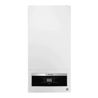
z Open the control panel cover.
z Remove the cover (fig. 33, pos. 1).
z Install the RC35 in the slot (fig. 33, pos. 2).
7.2 Installing function modules (accessories)
The following function modules (accessories) can be
connected to the boiler:
– Heat demand 0-10V module EM10
– Error reporting module EM10
– Switch module WM10
– Mixing module MM10.
The function modules (accessories) can be installed in two
ways:
– in the boiler (max. 2), see paragraph 7.2.1
– outside the boiler, see paragraph 7.2.2.
NOTICE
z It is not possible to connect more than one
room controller.
Fig. 33 Remove the cover and install the room controller in
the boiler (only for outdoor temperature-dependant
operation).
1
2
NOTICE
Refer to the installation instructions of the rele-
vant function modules for information about
installation and combination possibilities.