Start-up procedure9
Logamax plus GB162-80 kW/100 kW - Subject to modifications resulting from technical improvements!52
z Close the gas valve.
z Remove the gauge-connection tube and tighten the
screw plug on the testing nipple again.
z Open the gas valve again by pushing on the gas valve
and turning it ¼ rotation in a counterclockwise direction.
9.8 Check and adjust the gas/air ratio
z Open at least two thermostatic radiator valves, if present.
Do not switch ON the boiler.
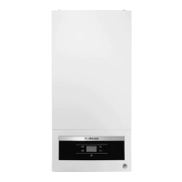
z Push on the control panel to open it.
z Switch OFF the heating system by pressing the main
switch of the BC10 basic controller (fig. 59, pos. 1).
z Close the gas valve (fig. 56).
z Turn the vent key through a quarter rotation to undo the
boiler door lock (fig. 47, see detailed picture).
z Push the fastener down (fig. 47) and open the boiler
door.
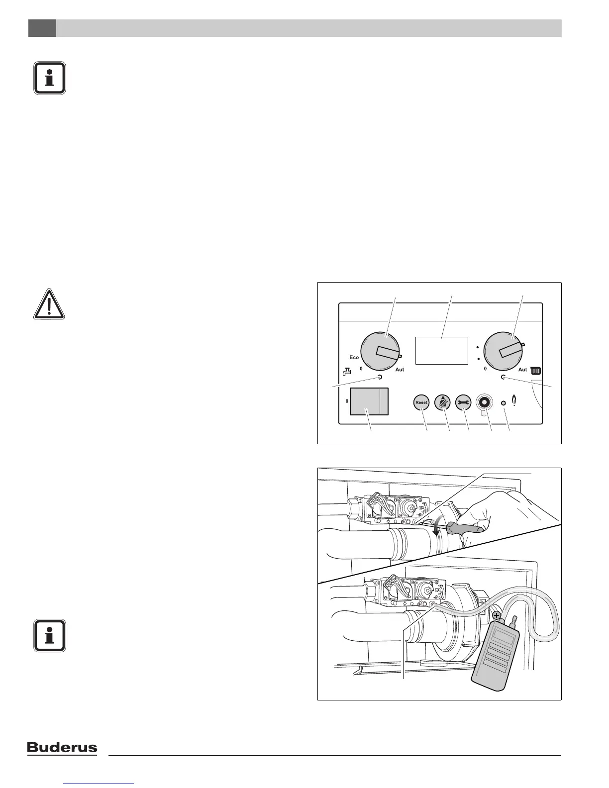
z Open the screw plug on the testing nipple for the burner
pressure by 2 turns (fig. 60, pos. 1).
z Set the pressure gauge to "0".
z Use a connection tube to connect the positive port of the
pressure gauge to the testing nipple for burner pressure
(fig. 60, pos. 2).
NOTICE
z Check the gas supply pipe or contact the rele-
vant gas utility company if the required supply
pressure is not available.
z If the supply pressure is too high, a gas pres-
sure regulator must be integrated upstream of
the gas fitting. Contact the gas utility
company.
Fig. 59 BC10 basic controller
888
1
123 456
11
10 98
7
110
140
130
120
90
100
130
170
150
90
110
190
WARNING
Damage to the boiler by incorrect adjustment of
the gas/air ratio.
z Adjust gas/air ratio ONLY with part load!
z Adjust gas/air ratio ONLY based on the gas/
air pressure differential and never based on
measured flue gas values such as CO/CO
2
/
NO
X
!
Fig. 60 Checking the gas/air ratio
2
1
NOTICE
Throughout the measuring operation, keep the
digital pressure gauge in the same position
(horizontal or vertical) in which it was reset
to "0".