Start-up procedure 9
Logamax plus GB162-80 kW/100 kW - Subject to modifications resulting from technical improvements! 53
z Slowly open the gas valve by pushing on the gas valve
and turning it ¼ rotation in an counterclockwise direction
(fig. 54).
z Switch ON the heating system by pressing the main
switch of the BC10 basic controller (fig. 59, pos. 1).
z Activate the Service mode in accordance with the
"Service mode" menu (table 9, page 42).
z Set the capacity to minimum (part load) according to the
"Service mode" menu (table 9, page 42).
z After the LED "Burner operation" (fig. 59, pos. 6) has lit
wait for one minute until the boiler is burning at part load.
z Read the differential pressure.
The differential pressure (p
Gas
– p
Air
) must be -
0.02 inch W.C. (- 5 Pa) (±0.02 inch W.C. = ± 5 Pa)
(read-out on pressure gauge: -0.04 – 0 inch W.C. = -10 –
0 Pa) (fig. 61).
z Enter the result in the commissioning log book (see
paragraph 15.1 "Start-up report", page 85).
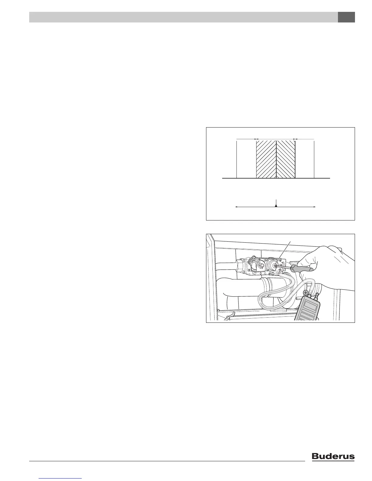
z If the gas/air ratio is incorrect, it must be adjusted on the
set screw (fig. 62, pos. 1). The set screw is located
behind the screw-on cover.
z Press the "Chimney sweep" button (fig. 59, pos. 3) until
the dot disappears from the display.
z Switch OFF the heating system by pressing the main
switch of the BC10 basic controller (fig. 59, pos. 1).
z Close the gas valve (fig. 56).
z Remove the measuring devices.
z Tighten the screw in the burner pressure measuring
nipple.
z Slowly open the gas valve by pushing on the gas valve
and turning it ¼ rotation in an counterclockwise direction
(fig. 54).
Fig. 61 Air/gas difference at part load
-15 -10 -5 0 5 (Pa)
-0,15 -0,10 -0,05 0,00 0,05 (mbar)
-0,06 -0,04 -0,02 0,00 0,02 (inch W.C.)
wrong correct wrong
turn counterclockwise turn clockwise
Fig. 62 Adjusting the gas/air ratio
1