Start-up procedure 9
Logamax plus GB162-80 kW/100 kW - Subject to modifications resulting from technical improvements! 51
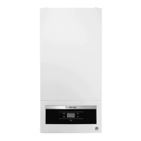
z Open the screw plug on the testing nipple for the gas inlet
pressure by 2 turns (fig. 57, pos. 1).
z Reset the digital pressure gauge to "0".
z Connect the pressure gauge connection tube to the posi-
tive port of the testing nipple (fig. 57, pos. 2).
z Slowly open the gas valve by pushing on the gas valve
and turning it ¼ rotation in an counterclockwise direction
(fig. 54, page 49). The gas valve is open when it is in the
vertical position.
z Switch ON the heating system by pressing the main
switch of the BC10 basic controller (fig. 58, pos. 1).
z Press and hold the "Chimney sweep" button (fig. 58,
pos. 3) (approx. two seconds), until the dot in the right-
hand bottom corner of the display (fig. 58, pos. 9)
appears. See also table 8, "Flue gas test", page 41.
z After the LED "Burner operation" (fig. 58, pos. 6) has lit
up wait for one minute until the boiler is burning at full
load.
z Measure the gas supply pressure and enter it in the start-
up report, page 85.
The gas supply pressure must be:
– for natural gas min. 7 inch W.C. (17.4 mbar),
max. 10.5 inch W.C. (26.1 mbar), nominal supply pres-
sure 8inchW.C. (19.9mbar).
– for LPG min. 8 inch W.C. (19.9 mbar),
max. 13 inch W.C. (32.3 mbar), nominal supply pres-
sure 11 inch W.C. (27.4 mbar).
z Press the "Service" button (fig. 58, pos. 4) repeatedly
until the temperature reading is shown in the display.
z Press the "Chimney sweep" button (fig. 58, pos. 3) to
clear the reading. Also see table 8, "Flue gas test",
page 41
Fig. 57 Measuring the gas supply pressure
1
2
NOTICE
Throughout the measuring operation, keep the
digital pressure gauge in the same position
(horizontal or vertical) in which it was reset
to "0".
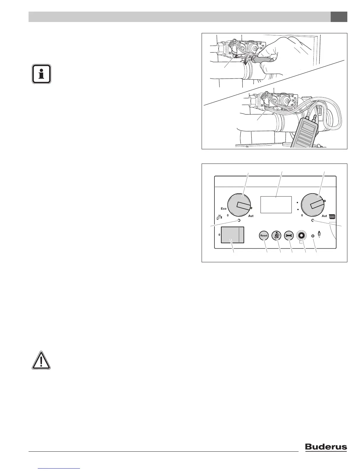
Fig. 58 BC10 basic controller
pos. 1: Main switch
pos. 2: "Reset" button
pos. 3: "Chimney sweep" button
pos. 4: "Service" button
pos. 5: Connection possibility for the diagnosis connector
pos. 6: LED "Burner operation"
pos. 7: LED "Central heat demand"
pos. 8: Space heating water temperature knob
pos. 9: Display
pos. 10: DHW temperature knob
pos. 11: LED "DHW demand"
888
1
123 456
11
10 98
7
110
140
130
120
90
100
130
170
150
90
110
190
WARNING
A leaking testing nipple causes explosive
fumes.
z Check the testing nipples used for leaks.
z Only use approved detection products to
locate leaks.