2 Installation
16 Installation and maintenance instructions Logano GE315 • Issue 02/2006
We reserve the right to make any changes due to technical modifications.
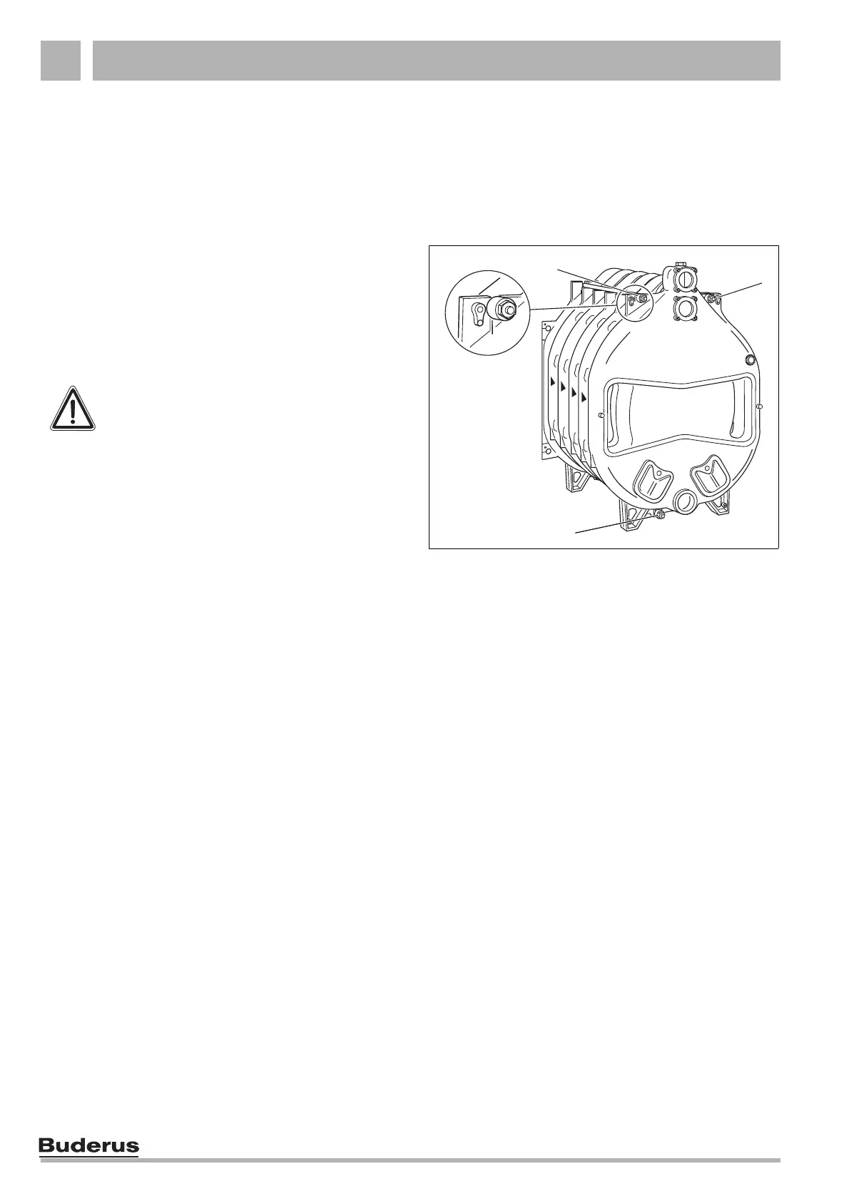
Fig. 17 Installation of the tie bars
2
3
1
Slacken the compression tool after the front section
has been assembled – but do not remove it yet!
Insert the tie bars before removing the compression
tool!
z Insert the three tie bars with the spring sets mounted
into the locations provided in the cast profiles
(Fig. 17, Item 1, 2 & 3).
Note when inserting the tie bars that the spring sets
are fitted at the back of the boiler.
z By hand screw one nut onto each of the tie bars
threads.
z Now tighten the nuts on each tie bar by 1 to 1 ½ turns.
z Align the boiler on the plinth or vibration absorbing
plinth in the horizontal and vertical plane (
see chapter
"2.3 Positioning", page 9).
z Remove the boiler compression tool.
The next step refers to the installation of the return
header (
see chapter "2.4.4 Slide the return header
into place (carton of installation components)",
page 18).
ATTENTION!
Use the spring sets only as complete sets,
i.e. do not undo!
 Loading...