Throw sifter Installation 19
© Copyright 2018 Bühler AG DFTA-66620-2-en-1803
4 Installation
4.1 Site requirements
Space requirements, floor openings, bearing surfaces and floor loads are in accord-
ance with separate planning documents.
4.2 Installation
• Block the assembly area against unauthorised access.
• Secure the surrounding area (remove any items that could cause someone to
stumble etc.).
• Allow sufficient clearance for performing installation and set-up tasks.
• The machine is installed directly to the floor. Fastening holes are provided on
the support plates of the machine frame. The machine must be exactly level hor-
izontally.
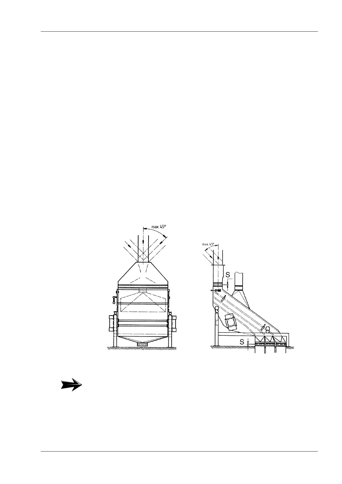
4.3 Product inlet
Product must be fed to the inlet directly into the middle of the machine so that the
product stream is distributed evenly over the entire sieve width. Best results are
achieved if the last piece of the inlet pipe is installed vertically to the machine. If that
is not possible, the inlet pipe can be connected at a light pitch (up to max. 45° from
vertical). If the vertical pipe piece to the inlet is longer than 1 m, an additional dead
box must be installed upstream of the sieve inlet.
Fig. 4.1
Note:
At distances greater than “S”, there is a danger that the rubber sleeves will wear
prematurely.