20 Installation Throw sifter
DFTA-66620-2-en-1803 © Copyright 2018 Bühler AG
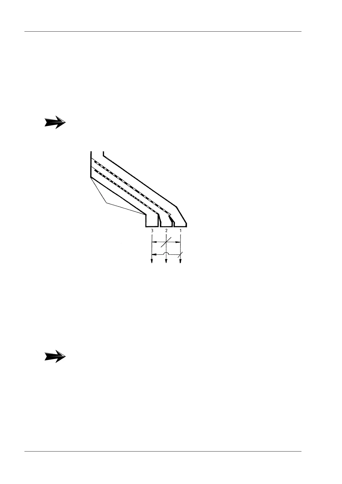
4.4 Product outlet
Depending on the design, the sieve has 3 to 4 outlets for overs from each sieve deck
(1) and (2) as well as one outlet for throughs (3). When installing the piping be abso-
lutely sure that the individual outlets are connected with each other via adjustable
gates depending on the use of the sieve. Observe the pipe construction diagram!
So that no vibrations are transmitted, the outlets must be connected to the piping
using the rubber sleeves provided. Dimension “S” between the pipes = 5 to 10 mm
(see Fig. 4.1,
19).
4.5 Energy connections
Installation must be carried out in accordance with local and national regulations.
4.5.1 Vibrator motors
To protect the vibrator motor, it is absolutely necessary to install a protective motor
switch or a contactor with thermal overcurrent relays.
Ensure that the connection cables are suspended loosely. Due to the danger of a
cable breaking caused by sieve vibrations, only rubber cables may be used. Con-
necting the limit switch (vibration monitoring) (refer to Fig. 4.3,
21). The distance
between the limit switch and the sieve box is approx. 1 mm.
Note:
At distances greater than “S”, there is a danger that the rubber sleeves will wear
prematurely.
Fig. 4.2
Note:
Due to the axially parallel arrangement of the two vibrator motors, these must run
in opposite rotation direction and must be electrically interlocked with each other
(see Chapter 4.5.2,
21).