24 Commissioning Throw sifter
DFTA-66620-2-en-1803 © Copyright 2018 Bühler AG
5.3 Vibrator motors
(Refer to Chap. 5.3.2,
25)
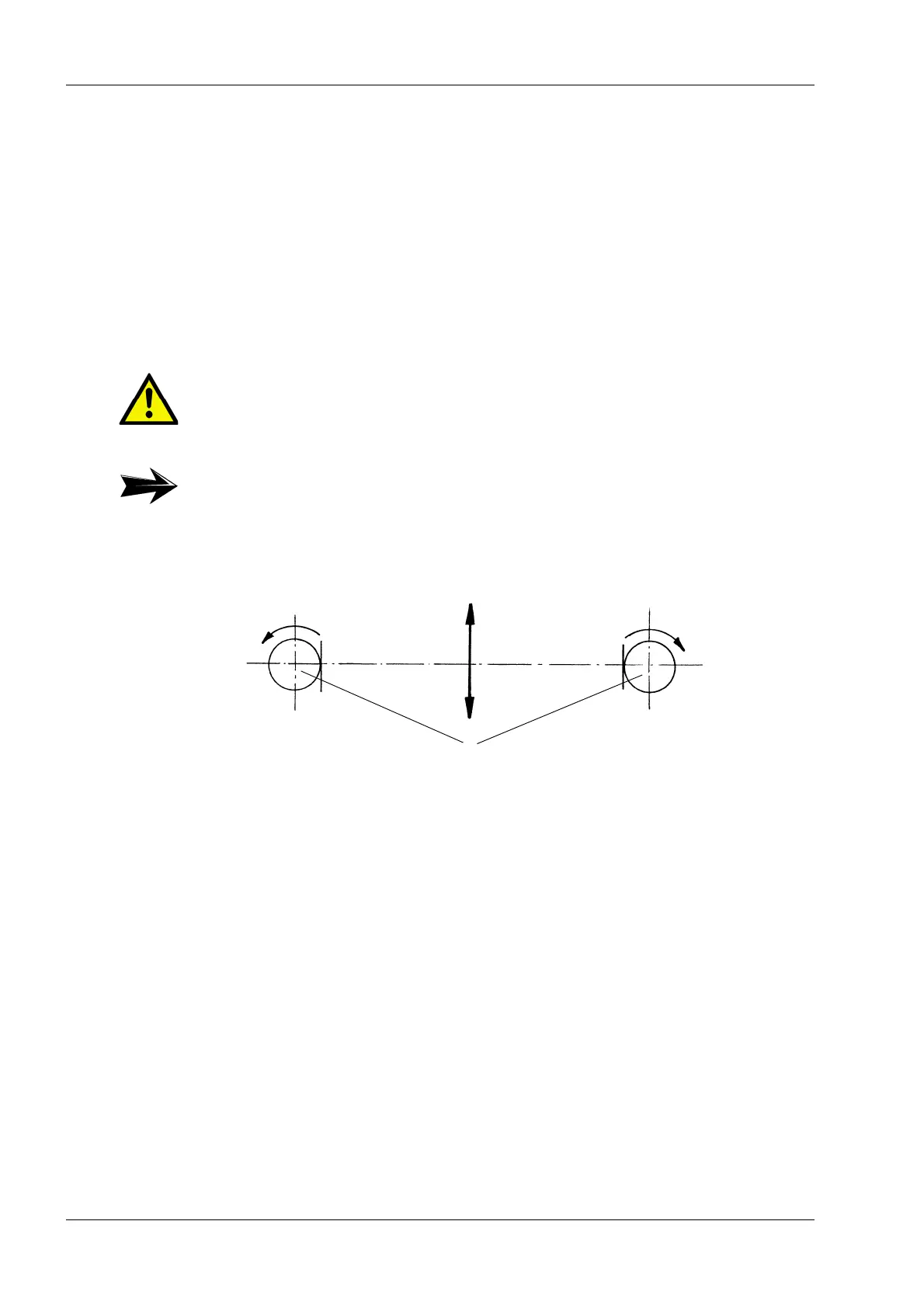
The stroke of the sieve box depends on the size of the centrifugal force from the
vibrator motors. The centrifugal force can be variably adjusted by changing the posi-
tion of one centrifugal weight (1) in relation to the other centrifugal weight (2). For
maximum centrifugal force, the centrifugal weights (1) and (2) are positioned so that
their contours are aligned exactly, one above the other.
The two centrifugal weights are adjusted at the factory so that the sieve box of the
machine oscillates at full load with the most effective stroke. Please check the
adjustment of the centrifugal weights again before commissioning the machine.
5.3.1 Direction of rotation
Caution!
The centrifugal weights (1) and (2) must be adjusted to exactly the same position
on both ends of the vibrator motors.
Note:
See manufacturer’s operating instructions.
Fig. 5.1
(1) Vibrator motor (2) Direction of movement of the sieve
box