32
Adjustment and commissioning
Type 8202/8222
9.4. Description of the display
9.4.1. Description of icons and LEDs
O
P
E
N
L
O
C
K
mV_pH
1423 mV
TempC
23.8 °C
ERR
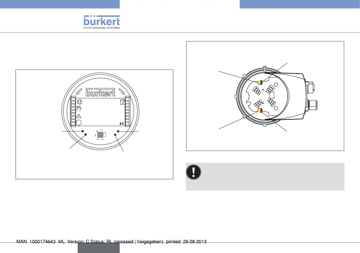
Red LED: shows
an error
not used
Yellow LED: shows that transis-
tor 1 is switched
Yellow LED: shows that transistor 2
is switched
Red LED: shows an error
Yellow LED: shows that
transistor 2 is switched
Green LED: shows that
the device is energized
Yellow LED: shows that
transistor 1 is switched
Fig. 27: Position of the icons and description of the LEDs
The LEDs of the display module are duplicated on the elec-
tronic board that is located under the display module: these
LEDs become visible when the transmitter is not equipped
with the display module.
English