16
Installation
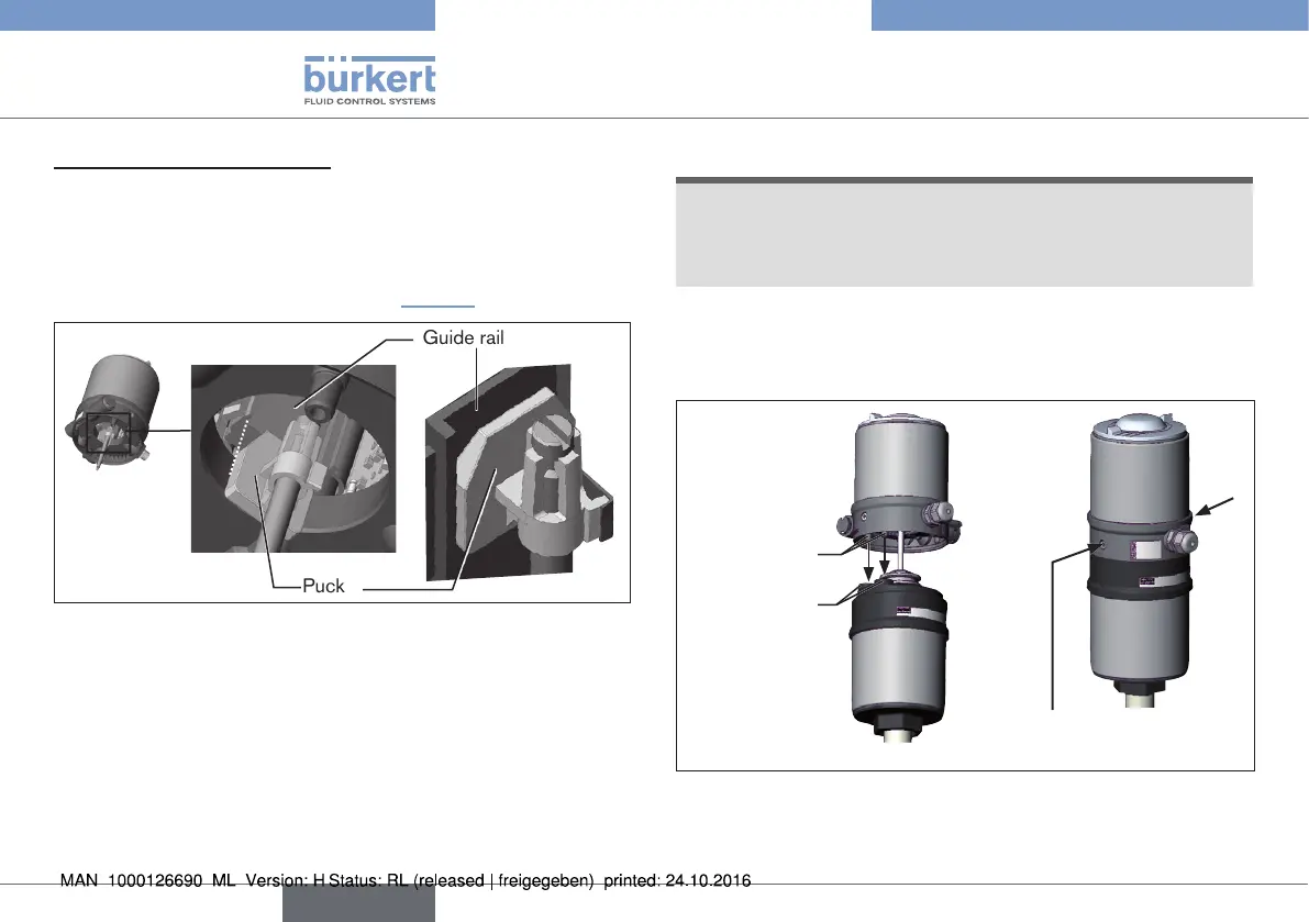
3. Install linear Remote Sensor
→ Align the puck and the Remote Sensor in such a way that
1. the puck engages in the guide rail of the Remote
Sensor and
2. the connection pieces of the Remote Sensor engage in the
pilot air ports of the actuator (see “Fig. 12”)
Guide rail
Puck
Fig. 11: Aligning the puck
→ Push the Remote Sensor without turning it onto the actuator until
no gap is visible on the form seal.
NOTE!
Too high torque when screwing in the fastening screw does
not ensure degree of protection IP65 / IP67.
▶ The fastening screws may be tightened to a maximum torque
of 1.5 Nm only.
→ Attach the Remote Sensor to the actuator using the two side
fastening screws. In doing so, tighten the screws only hand-tight
(max. torque: 1.5 Nm).
Connection
pieces
Pilot air
ports
Fastening screws
max. 1.5 Nm
Fig. 12: Installation of linear Remote Sensor, series 2103, 2300
and 2301
english
Type 8798