17
Installation
8.2.2 Attachment to process valves to
series 26xx and 27xx
Procedure:
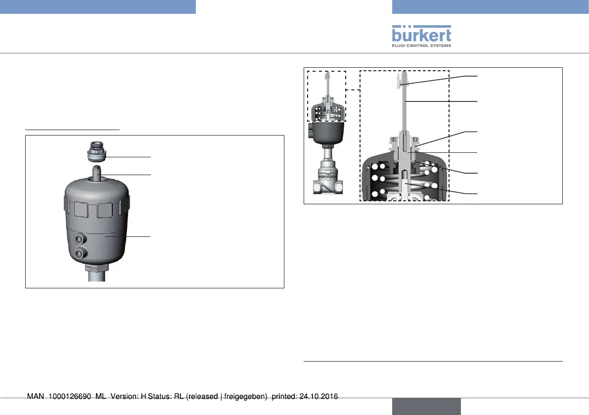
1. Install switch spindle
Guide piece
Spindle extension
Actuator
Fig. 13: Installing the switch spindle, series 26xx and 27xx - 1
→ Unscrew the already fitted guide piece from the actuator
(if present).
→ Remove intermediate ring (if present).
→ Press the O-ring downwards into the cover of the actuator.
Guide element
O-ring
Spindle extension
Puck
Switch spindle
Spindle (actuator)
Fig. 14: Installing the switch spindle, series 26xx and 27xx - 2
→ Actuator size 125 and bigger:
remove existing spindle extension and replace with the new one.
To do this, apply some screw locking paint (Loctite 290) in the
tapped bore of the spindle extension.
→ Screw the guide element into the cover of the actuator using a
face wrench
2)
(torque: 8.0 Nm).
→ To secure the switch spindle, apply some screw locking paint
(Loctite 290) to the thread of the switch spindle.
→ Screw the switch spindle onto the spindle extension. To do this,
there is a slot on the upper side (maximum torque: 1 Nm).
→ Push the puck onto the switch spindle until it engages.
2) journal Ø: 3 mm; journal gap: 23.5 mm
english
Type 8798