49
Adjustment and start-up
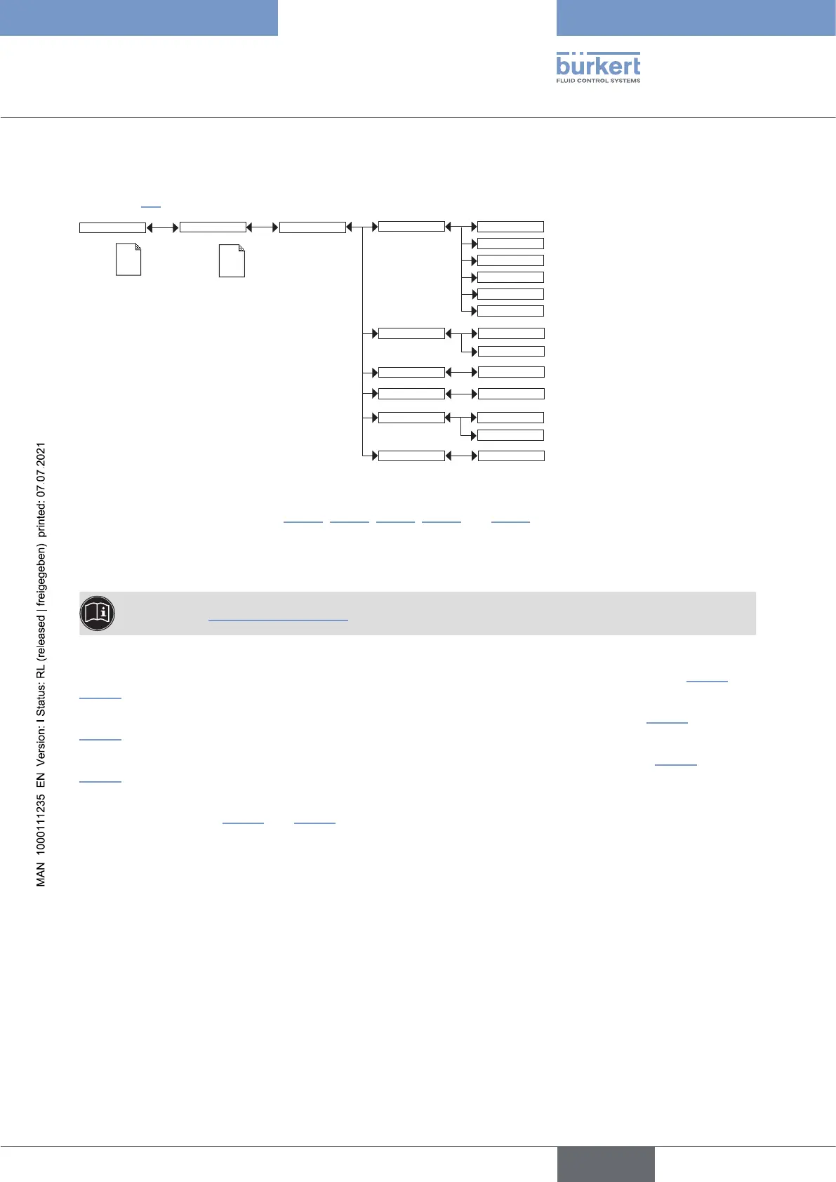
9.11.10 Setting the parameters of the transistor outputs
See chpt. 9.9 to access the Parameters menu.
Param
This is
when the
device is be-
ing parame-
tered............
....................
This is
when the
device is be-
ing parame-
tered............
....................
Outputs
TR1 / TR2
PVar:
Low:
INPUT
High:
INPUT
Delay: INPUT
Contact:
CondS
TDSppm
TempC
TempF
CondR
Warning
Mode: Hysteresis
Window
Normally open
Normally closed
PVAR: choose a process value (impedance in .cm, conductivity in S/cm, temperature in °C, temperature in °F or
total dissolved solids in ppm) associated with transistor output 1 or transistor output 2 respectively or associate
the “warning” message (see chpt. 9.12.4, 9.13.2, 9.13.3, 9.13.4 and 9.15.1) with transistor output 1 or transistor
output 2 respectively.
If the selected transistor output is linked to the “warning” event, the transistor switches as soon as such an event
is generated by the device.
See also chpt. 10.3 Solving a problem.
MODE: choose the operating, hysteresis or window, for transistor output 1 or transistor output 2 (see Fig. 33 and
Fig. 34).
LOW: enter the low switching threshold value for transistor output 1 or transistor output 2 (see Fig. 33 and
Fig. 34).
HIGH: enter the high switching threshold value for transistor output 1 or transistor output 2 (see Fig. 33 and
Fig. 34).
CONTACT: choose the type of off-position (normally open, NO, or normally closed, NC) of transistor output 1 or
transistor output 2 (see Fig. 33 and Fig. 34).
DELAY: choose the value of the time delay prior to switching for each transistor output.
Switching only occurs if one of the thresholds, high or low (functions “High” or “Low”), is exceeded for a duration
longer than this time delay. The time delay before switching is applicable to both output thresholds.
English
Type 8222 ELEMENT