52
Adjustment and start-up
In practice, when the device is in mode “Hold”:
• the
HOLD
!
icon is displayed in place of the icon;
• the current emitted on each 4...20 mA output is fixed at the value of the last measurement of the physical
parameter associated with each output;
• each transistor output is fixed at the status acquired at the moment the Hold function is activated;
• the device is in Hold mode until the HOLD function is deactivated.
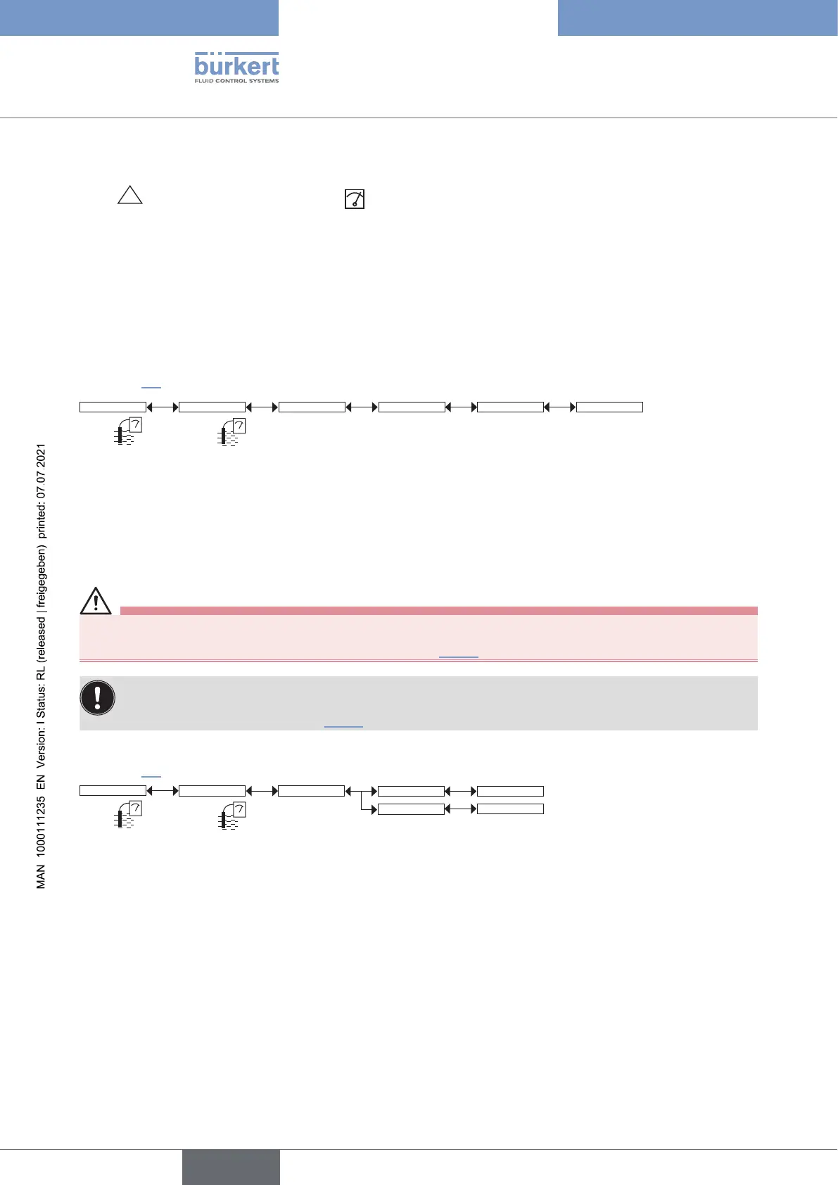
9.12.2 Modifying the Calibration menu access code
See chpt. 9.9 to access the Calibration menu.
Code 0*** Confirm code 0***Calib System
Enter the new
code
Confirm the new
code
If the default code (0000) is entered, the code will not be requested to access the menu.
9.12.3 Adjusting the current outputs
Warning
Risk of injury due to wrong adjustment.
▶ Make sure that the Hold mode is disabled. Refer to chpt. 9.12.1.
On a device variant with a single M12 fixed connector and if the power supply is lower than 16 V DC,
before adjusting the current output, make sure that the light intensity of the display (“Backlight” parameter)
is lower than 14 %. Refer to chpt. 9.11.7.
See chpt. 9.9 to access the Calibration menu.
Outputs AC1 / AC2
4mA:
20mA:
INPUT
INPUT
Calib
4mA: adjust the current output 1 or current output 2 for 4 mA.
When the “4mA” function is selected, the device generates a current of 4 mA: measure the current emitted by
the 4...20 mA output using a multimeter and enter the value given by the multimeter in the function “AC1.4mA” or
“AC2.4mA”.
20mA: adjust the current output 1 or current output 2. for 20 mA
When the “20mA” function is selected, the device generates a current of 20 mA: measure the current emitted by
the 4...20 mA output using a multimeter and enter the value given by the multimeter in the function “AC1.20mA”
or “AC2.20mA”.
English
Type 8222 ELEMENT