46
Electrical installation and Wiring
2
A
B
C
6
CURRENT
SOURCESINK
BINARY
PE PEPE
PE
DI1
DI2
DI3
DI4
DO4
ISOG
FLOW
SENSOR
L+ L- PE P- P+
NC
Iout
PULSE
DO1
Supply
12..36Vdc
Univ
Batch
(AO1)
SUPPLY
NC
COIL
PULSE
INPUT
NPN/PNP
213PE
+-
SENSOR
SUPPLY
LOAD
+5V
L+
(L+)-12V
COIL/PNP
39K
470
2.2K
SENSOR TYPE
COIL NPN/PNP
DO2
DO3
OFFON
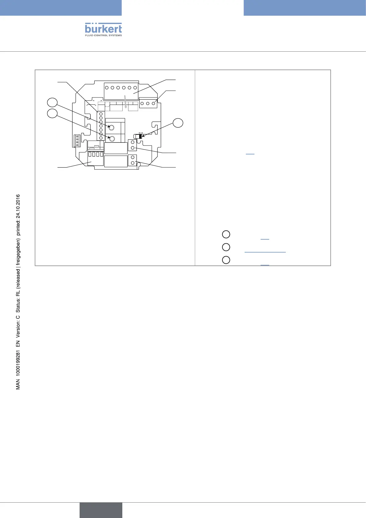
3
Terminal block 1
• NC: not connected
• L+: V+ (positive voltage)
• L-: 0V (power supply ground)
• PE: protective earth, factory wired
• P-: negative transistor output (DO1)
• P+: positive transistor output (DO1)
Terminal block 2
PE: shieldings of the power supply cable and the
input / output cables
Terminal block 3: wiring the DO2 relay output.
Terminal block 4: wiring the DO3 relay output.
Terminal block 5 "FLOW SENSOR": Wiring the
remote flow sensor. The wiring depends on the
type of output signal originating from the flow
sensor: See chap. 8.9.
Terminal block 6 "BINARY"
• DI1 to DI4: 4 digital inputs
• DO4: transistor output
• ISOG: ISOGND, ground common to the 4
digital inputs and the transistor output DO4.
• PE: cable shielding
Selector
A
: see chap. 8.9.
Selector
B
: see Tab. 3, page 54
Selector
C
: see chap. 8.9.
Fig. 23 : Terminal assignment of a 12...36 V DC fed version for the 8025 Batch in panel-mounted or in wall-mounted version
English
Type 8025 - 8035 - SE35 BATCH