47
Electrical installation and Wiring
LN
LN
230V
230V
230V
A
3
B
C
CURRENT
SOURCESINK
BINARY
PE PEPE
PE
DI1
DI2
DI3
DI4
DO4
ISOG
FLOW
SENSOR
L+ L- PE P- P+
NC
Iout
PULSE
DO1
Supply
12..36Vdc
Univ
Batch
(AO1)
SUPPLY
NC
COIL
PULSE
INPUT
NPN/PNP
213PE
+-
SENSOR
SUPPLY
LOAD
+5V
L+
(L+)-12V
COIL/PNP
39K
470
2.2K
SENSOR TYPE
COIL NPN/PNP
DO2
DO3
OFF ON
5
D
7
4
T 125 mA
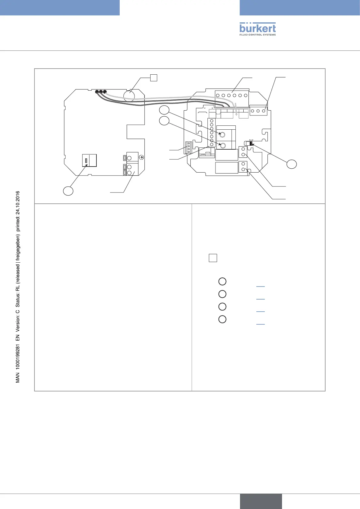
Terminal block 1
PE: shieldings of the power supply cable and the input /
output cables
Terminal block 2
• NC: not connected
• L+: V+ (red wire, factory wired)
• L-: 0V (black wire, factory wired)
• PE: protective earth (green/yellow wire, factory wired)
• P-: negative transistor output (DO1)
• P+: positive transistor output (DO1)
Connector 3: connection of the flow sensor
Terminal block 4 "BINARY"
• DI1 to DI4: 4 digital inputs
• DO4: transistor output
• ISOG: ISOGND, ground common to the 4 digital inputs
and the transistor output DO4.
• PE: cable shielding
Terminal block 5: wiring the DO2 relay output.
Terminal block 6: wiring the DO3 relay output.
Terminal block 7: wiring of the 115/230 V AC
power supply
Mark
8
: time-delay fuse to protect the
115/230 V AC power supply
Selector
A
: see chap. 8.6;
Selector
B
: see chap. 8.6;
Selector
C
: see chap. 8.6.
Selector
D
: see chap. 8.6.
Fig. 24 : Terminal assignment of a 115/230 V AC fed version for the 8025 Batch in compact version, for the 8035 Batch and
for the SE35 Batch
English
Type 8025 - 8035 - SE35 BATCH