Do you have a question about the Caen N1471 and is the answer not in the manual?
Provides an overview of the Mod. N1471, its features, and capabilities.
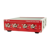
Details the housing and physical form factor of the N1471 module.
Lists the voltage and current specifications required for the device.
Illustrates and describes the physical layout of the front and back panels.
Details the physical connections on the front panel for control and communication.
Describes the status indicators like ALARM and INTERLOCK for HV channels.
Details the communication interfaces like RS485 and RS232 for remote control.
Describes the physical connections on the rear panel, including HV output.
Provides a comprehensive table of all technical specifications for the N1471 module.
Covers general board parameters that can be programmed for module operation.
Details parameters like power status, termination, baud rate, and control mode.
Explains parameters for individual channels like Vmon, Imon, Vset, and Iset.
Details the process of connecting HV cables and enabling module outputs.
Explains how to access and modify general module settings like control mode and termination.
Guides on setting individual channel parameters like VSET, ISET, and Ramp rates.
Allows broadcasting parameter values to all channels simultaneously for efficient configuration.
Details the procedure for calibrating the current monitor for accurate low-current measurements.
Explains how to control the module remotely via USB or RS485.
Covers communication via USB, RS232, and RS485 serial interfaces for remote operation.
Explains RS232 serial communication setup and daisy chaining capabilities.
Details RS485 serial communication and how to build daisy chains of modules.
Describes Ethernet communication setup via the NIM8301 crate and cable adapter.
Guides on establishing and controlling communication sessions and menus.
Details the main menu structure for remote control operations and parameter selection.
Explains accessing board status and general settings remotely via the General Menu.
Describes how to monitor and set individual channel parameters remotely.
Procedure for upgrading the module's firmware remotely using a PC.
Instructions for formatting the module's EEPROM remotely to reset settings.
Specifies the structure and fields for sending commands to the module.
Details the format of responses received from the module, including errors.
Lists specific commands for monitoring individual channel parameters.
Explains the meaning of individual bits within the module's status word.
Lists specific commands for monitoring module-level parameters and status.
Provides the command strings for setting individual channel parameters.
Lists the command strings for setting module-level parameters.
Details how to select the output polarity for each channel using internal jumpers.
Explains the function of internal DIP switches for configuration.
Describes the DIP switch used to configure Local Bus termination for daisy chaining.
Explains the DIP switch for adapting RS485 signals to RS232 communication.
| 117/230 VAC selectable | Yes |
|---|---|
| +6V | Not applicable |
| -6V | Not applicable |
| +12V | Not applicable |
| -12V | Not applicable |
| +24V | Not applicable |
| -24V | Not applicable |
| Number of Channels | 8 |